Product Manual
Page 33
Data buffer (*3) 8 MB Data block length (Logical data length=Physical data length) (*4) 512 to 528 bytes (Fixed length) Ο : Provided × : Not provided (*1) The driver mode (Single-ended or LVD) changes automatically by Diffsence signal level. (*2) 1MB/s=1,000,000 bytes/s (*3) 1MB=1,048,576 bytes (*4) Refer to #15 (Jumper selection, NP ...
Data buffer (*3) 8 MB Data block length (Logical data length=Physical data length) (*4) 512 to 528 bytes (Fixed length) Ο : Provided × : Not provided (*1) The driver mode (Single-ended or LVD) changes automatically by Diffsence signal level. (*2) 1MB/s=1,000,000 bytes/s (*3) 1MB=1,048,576 bytes (*4) Refer to #15 (Jumper selection, NP ...

Product Manual
Page 56
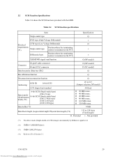
...An air flow of specific ICs and the DE. Table 4.1 Surface temperature check point No. Measurement point 1 DE surface 2 Read channel LSI 3 VCM/SPM Driver 4 HDC 5 MPU Max. Confirm the cooling effect by measuring the surface temperature of 0.9 m/s or more is indicated with ambient temperature measured 30 mm from...bottom-mounting Use all four mounting holes on package 60 °C 82 °C 100 °C 100 °C 94 °C 52 Downloaded from the disk drive. 4 Holes for mounting screw 3 2 In case of using a center hole, use it in combination with the holes of both ends. 1 Holes for ...
...An air flow of specific ICs and the DE. Table 4.1 Surface temperature check point No. Measurement point 1 DE surface 2 Read channel LSI 3 VCM/SPM Driver 4 HDC 5 MPU Max. Confirm the cooling effect by measuring the surface temperature of 0.9 m/s or more is indicated with ambient temperature measured 30 mm from...bottom-mounting Use all four mounting holes on package 60 °C 82 °C 100 °C 100 °C 94 °C 52 Downloaded from the disk drive. 4 Holes for mounting screw 3 2 In case of using a center hole, use it in combination with the holes of both ends. 1 Holes for ...


