Product Manual
Page 7
... during operation and remain hot immediately after turning off before connecting or disconnecting 82 cables. 2. Do not change the setting of the CN2 setting terminal (NP model only) 3. Check that the SCSI device with the terminating resistor is shipped from www.Manualslib.com manuals search engine Important Alert Items Important Alert...
... during operation and remain hot immediately after turning off before connecting or disconnecting 82 cables. 2. Do not change the setting of the CN2 setting terminal (NP model only) 3. Check that the SCSI device with the terminating resistor is shipped from www.Manualslib.com manuals search engine Important Alert Items Important Alert...
Product Manual
Page 12
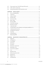
4.3.2 4.3.3 4.3.4 68-pin connector type 16-bit SCSI model (NP model 60 Cable connector requirements 67 External operator panel (on NP model drives only 68 CHAPTER 5 INSTALLATION 71 5.1 Notes on Handling HDDs 71 5.2 Connections...73 5.3 Setting Terminals ...75 5.3.1 SCSI ID setting...76 5.3.2 Each mode setting ...78 5.3.3 Mode settings ...80 5.4 Mounting HDDs...81 5.4.1 Check before mounting ...81...
4.3.2 4.3.3 4.3.4 68-pin connector type 16-bit SCSI model (NP model 60 Cable connector requirements 67 External operator panel (on NP model drives only 68 CHAPTER 5 INSTALLATION 71 5.1 Notes on Handling HDDs 71 5.2 Connections...73 5.3 Setting Terminals ...75 5.3.1 SCSI ID setting...76 5.3.2 Each mode setting ...78 5.3.3 Mode settings ...80 5.4 Mounting HDDs...81 5.4.1 Check before mounting ...81...
Product Manual
Page 13
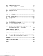
...-00), (B-44-xx), (B-47-xx), (B-48-00), (B-49-00), (B-4D-xx) and (B-4E-00): SCSI interface error 116 APPENDIX A SETTING TERMINALS 117 A.1 Setting Terminals (on NP model only 118 APPENDIX B CONNECTOR SIGNAL ALLOCATION 119 B.1 SCSI Connector Signal Allocation: SCA2 type LVD 16-bit SCSI 120 B.2 SCSI Connector Signal Allocation: 68-pin...
...-00), (B-44-xx), (B-47-xx), (B-48-00), (B-49-00), (B-4D-xx) and (B-4E-00): SCSI interface error 116 APPENDIX A SETTING TERMINALS 117 A.1 Setting Terminals (on NP model only 118 APPENDIX B CONNECTOR SIGNAL ALLOCATION 119 B.1 SCSI Connector Signal Allocation: SCA2 type LVD 16-bit SCSI 120 B.2 SCSI Connector Signal Allocation: 68-pin...

Product Manual
Page 14
...13 Figure 4.14 Figure 4.15 Figure 4.16 Figure 4.17 Figure 4.18 Figure 4.19 Figure 4.20 Figure 4.21 Figure 4.22 NC model dimensions...48 NP model dimensions ...49 HDD orientations...50 Mounting frame structure ...51 Limitation of side-mounting 52 Surface temperature measurement points 53 Current waveform (Spin-up 54...(2 56 Power on/off sequence (3 56 AC noise filter (recommended 58 NC connectors location ...58 SCA2 type 16-bit SCSI connector 59 NP connectors and terminals location 60 68-pin type 16-bit SCSI interface connector 61 Power supply connector (68-pin type 16-bit SCSI 61 ...
...13 Figure 4.14 Figure 4.15 Figure 4.16 Figure 4.17 Figure 4.18 Figure 4.19 Figure 4.20 Figure 4.21 Figure 4.22 NC model dimensions...48 NP model dimensions ...49 HDD orientations...50 Mounting frame structure ...51 Limitation of side-mounting 52 Surface temperature measurement points 53 Current waveform (Spin-up 54...(2 56 Power on/off sequence (3 56 AC noise filter (recommended 58 NC connectors location ...58 SCA2 type 16-bit SCSI connector 59 NP connectors and terminals location 60 68-pin type 16-bit SCSI interface connector 61 Power supply connector (68-pin type 16-bit SCSI 61 ...
Product Manual
Page 15
Figure 4.23 External operator panel circuit example 68 Figure 5.1 Figure 5.2 Figure 5.3 Figure 5.4 Figure 5.5 SCSI bus connections ...74 Setting terminals location (on NP models only 75 CN2 setting terminal (on NP models only 76 Checking the SCSI connection (A 85 Checking the SCSI connection (B 86 Figure 6.1 Figure 6.2 Figure 6.3 Figure 6.4 Test flowchart ...103 Single HDD packaging...108 Multi-box packaging...110 Fraction packaging ...111 Figure 7.1 Sense data format...114 C141-E270 11 Downloaded from www.Manualslib.com manuals search engine
Figure 4.23 External operator panel circuit example 68 Figure 5.1 Figure 5.2 Figure 5.3 Figure 5.4 Figure 5.5 SCSI bus connections ...74 Setting terminals location (on NP models only 75 CN2 setting terminal (on NP models only 76 Checking the SCSI connection (A 85 Checking the SCSI connection (B 86 Figure 6.1 Figure 6.2 Figure 6.3 Figure 6.4 Test flowchart ...103 Single HDD packaging...108 Multi-box packaging...110 Fraction packaging ...111 Figure 7.1 Sense data format...114 C141-E270 11 Downloaded from www.Manualslib.com manuals search engine
Product Manual
Page 16
...ID setting...77 Setting SCSI terminator power supply (NP model 78 Motor start mode setting...78 Write protect setting (NP model 79 Setting of the SCSI interface operation mode (NP model 79 Setting the bus width of the SCSI interface (NP model 79 Default mode settings (by CHANGE ...diagnostic functions ...95 System-level field troubleshooting 106 HDD troubleshooting ...107 Table 7.1 Definition of sense data ...115 Table A.1 CN2 setting terminal (on NP model drives only 118 Table B.1 Table B.2 SCSI connector (SCA2 type LVD 16-bit SCSI): CN1 120 SCSI connector (68-pin type LVD 16-bit ...
...ID setting...77 Setting SCSI terminator power supply (NP model 78 Motor start mode setting...78 Write protect setting (NP model 79 Setting of the SCSI interface operation mode (NP model 79 Setting the bus width of the SCSI interface (NP model 79 Default mode settings (by CHANGE ...diagnostic functions ...95 System-level field troubleshooting 106 HDD troubleshooting ...107 Table 7.1 Definition of sense data ...115 Table A.1 CN2 setting terminal (on NP model drives only 118 Table B.1 Table B.2 SCSI connector (SCA2 type LVD 16-bit SCSI): CN1 120 SCSI connector (68-pin type LVD 16-bit ...

Product Manual
Page 18
...bit SCSI The HDD has 16-bit data bus width (16-bit SCSI), which have the wide transfer function suitable for NP model) • 16-bit SCSI: 16 drives max. 14 Downloaded from www.Manualslib.com manuals search engine C141-E270 For the ultra SCSI model, number of the HDD.... 1.1 Standard Features (1) Compactness Since the SCSI controller circuit is embedded in the standard 3.5-inch hard disk drive form factor, the HDD is available only with the Restriction of the use of certain Hazardous Substances in electrical and electronic equipment (RoHS) ...
...bit SCSI The HDD has 16-bit data bus width (16-bit SCSI), which have the wide transfer function suitable for NP model) • 16-bit SCSI: 16 drives max. 14 Downloaded from www.Manualslib.com manuals search engine C141-E270 For the ultra SCSI model, number of the HDD.... 1.1 Standard Features (1) Compactness Since the SCSI controller circuit is embedded in the standard 3.5-inch hard disk drive form factor, the HDD is available only with the Restriction of the use of certain Hazardous Substances in electrical and electronic equipment (RoHS) ...
Product Manual
Page 24
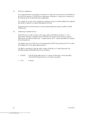
...multiSCSI devices. (2) Addressing of SCSI ID and LUN are as follows: • SCSI ID: • LUN: 8-bit SCSI:Selectable from 0 to 7 (option for NP model, switch selectable) 16-bit SCSI:Selectable from 0 to select the peripheral device for each logical unit. A unique address (LUN: logical unit number) is a ...Each SCSI device on which multiple host computers that operate as logical unit. The HDD is constructed so that the whole volume of disk drive is assigned for input/output operation. For example, the system can be configured as multi-host system on the bus has its own ...
...multiSCSI devices. (2) Addressing of SCSI ID and LUN are as follows: • SCSI ID: • LUN: 8-bit SCSI:Selectable from 0 to 7 (option for NP model, switch selectable) 16-bit SCSI:Selectable from 0 to select the peripheral device for each logical unit. A unique address (LUN: logical unit number) is a ...Each SCSI device on which multiple host computers that operate as logical unit. The HDD is constructed so that the whole volume of disk drive is assigned for input/output operation. For example, the system can be configured as multi-host system on the bus has its own ...
Product Manual
Page 33
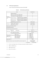
...driver mode (Single-ended or LVD) changes automatically by Diffsence signal level. (*2) 1MB/s=1,000,000 bytes/s (*3) 1MB=1,048,576 bytes (*4) Refer to #15 (Jumper selection, NP model) #0 fixed Ο 20 MB/s max. Ο 40 MB/s max. Ο 40 MB/s max. Ο 80 MB/s max. Ο 160 ... Differential type Position where the terminating resistor is mounted on the PCA × TERMPWR signal send function Ο (NP model) Connector 68-pin P cable connector 80-pin SCA2 connector Ο (NP model) Ο (NC model) Data bus parity (Data bus CRC) Ο Bus arbitration function Ο ...
...driver mode (Single-ended or LVD) changes automatically by Diffsence signal level. (*2) 1MB/s=1,000,000 bytes/s (*3) 1MB=1,048,576 bytes (*4) Refer to #15 (Jumper selection, NP model) #0 fixed Ο 20 MB/s max. Ο 40 MB/s max. Ο 40 MB/s max. Ο 80 MB/s max. Ο 160 ... Differential type Position where the terminating resistor is mounted on the PCA × TERMPWR signal send function Ο (NP model) Connector 68-pin P cable connector 80-pin SCA2 connector Ο (NP model) Ο (NC model) Data bus parity (Data bus CRC) Ο Bus arbitration function Ο ...

Product Manual
Page 53
The value marked with (*) indicates the dimension between mounting holes on the bottom face. [Unit: mm] Figure 4.2 NP model dimensions C141-E270 49 Downloaded from www.Manualslib.com manuals search engine
The value marked with (*) indicates the dimension between mounting holes on the bottom face. [Unit: mm] Figure 4.2 NP model dimensions C141-E270 49 Downloaded from www.Manualslib.com manuals search engine
Product Manual
Page 61
(4) Sequential starting 0 12 s 24... For the NP model drives, the spindle motors should be started by setting CN1-38 pin to ... started sequentially using of current flows in the power supply unit at more to 200 mA. b) Turn on the HDD (NP model only). See Subsection 5.3.2 for the terminating resistor is recommended. For details of this selection. s 180 s (5) Power... 3.1.10 "START/STOP UNIT (1B)" of up to start control mode, see Subsection 5.3.2. For the NC model drives, the spindle motors should be designed with a setting terminal on the +12V DC power in the +12 VDC line...
(4) Sequential starting 0 12 s 24... For the NP model drives, the spindle motors should be started by setting CN1-38 pin to ... started sequentially using of current flows in the power supply unit at more to 200 mA. b) Turn on the HDD (NP model only). See Subsection 5.3.2 for the terminating resistor is recommended. For details of this selection. s 180 s (5) Power... 3.1.10 "START/STOP UNIT (1B)" of up to start control mode, see Subsection 5.3.2. For the NC model drives, the spindle motors should be designed with a setting terminal on the +12V DC power in the +12 VDC line...

Product Manual
Page 64
...) (1) Connectors Figures 4.15 show the locations of connectors and terminals on the 68-pin connector type 16-bit SCSI model (NP model). • Power supply connector • SCSI connector • External operator panel connector External operator panel connector (CN2) ...Power supply connector (CN1) External operator panel connector (CN1) SCSI connector (CN1) Figure 4.15 NP connectors and terminals location (2) SCSI connector and power supply connector a. 16-bit SCSI The connector for the signal assignments on the physical/electrical...
...) (1) Connectors Figures 4.15 show the locations of connectors and terminals on the 68-pin connector type 16-bit SCSI model (NP model). • Power supply connector • SCSI connector • External operator panel connector External operator panel connector (CN2) ...Power supply connector (CN1) External operator panel connector (CN1) SCSI connector (CN1) Figure 4.15 NP connectors and terminals location (2) SCSI connector and power supply connector a. 16-bit SCSI The connector for the signal assignments on the physical/electrical...

Product Manual
Page 71
...P0.635 Fujikura Power supply cable (CN1) Cable socket housing 1-480424-0 Contact 170148-1 Tyco Electronics AMP Tyco Electronics S2 AMP NP Cable (AWG18 to 24) Cable socket housing A3B-12D-2C HIROSE ELECTRIC External operator panel (CN1) Contact A3B-2630SCC HIROSE ...ELECTRIC S3 Cable (AWG26 to 36) Cable socket housing FCN-723J024/2M FUJITSU TAKAMIZAWA External operator panel (CN2) Contact FCN-723J-G/AM FUJITSU TAKAMIZAWA S4 Cable (AWG28) (*1) See Figure 4.22. (1) SCSI cable Refer to Section 1.3 "Physical Requirements" ...
...P0.635 Fujikura Power supply cable (CN1) Cable socket housing 1-480424-0 Contact 170148-1 Tyco Electronics AMP Tyco Electronics S2 AMP NP Cable (AWG18 to 24) Cable socket housing A3B-12D-2C HIROSE ELECTRIC External operator panel (CN1) Contact A3B-2630SCC HIROSE ...ELECTRIC S3 Cable (AWG26 to 36) Cable socket housing FCN-723J024/2M FUJITSU TAKAMIZAWA External operator panel (CN2) Contact FCN-723J-G/AM FUJITSU TAKAMIZAWA S4 Cable (AWG28) (*1) See Figure 4.22. (1) SCSI cable Refer to Section 1.3 "Physical Requirements" ...

Product Manual
Page 72
... referring to CN2. (LED) Figure 4.23 External operator panel circuit example 68 Downloaded from www.Manualslib.com manuals search engine C141-E270 (4) External operator panel (NP model only) The external operator panel is installed only when required for 16-bit SCSI) (*1) For connecting the external LED to the recommendation if necessary... connector of the HDD: Pins 21, 22 and pins 01 through 08 in CN2 and pins A1 through A12 in CN1. 4.3.4 External operator panel (on NP model drives only) A recommended circuit of the external operator panel is shown in Figure 4.23.
... referring to CN2. (LED) Figure 4.23 External operator panel circuit example 68 Downloaded from www.Manualslib.com manuals search engine C141-E270 (4) External operator panel (NP model only) The external operator panel is installed only when required for 16-bit SCSI) (*1) For connecting the external LED to the recommendation if necessary... connector of the HDD: Pins 21, 22 and pins 01 through 08 in CN2 and pins A1 through A12 in CN1. 4.3.4 External operator panel (on NP model drives only) A recommended circuit of the external operator panel is shown in Figure 4.23.
Product Manual
Page 76
... that the HDD is turned off. c) Place and keep removed screws and other parts where they are pins 9, 10 (Write Protect) in CN2. (NP model) b) Do not move the HDD when power is on. b) Minimize the delivery distance after power is free from www.Manualslib.com manuals search engine... a) Do not attempt to use one of all maintenance work area. b) It is recommended to connect or disconnect connections when power is turned on hard material such as those at delivery cannot be altered are not damaged. (5) Delivery a) When delivering the HDD, provide packaging and do not turn it...
... that the HDD is turned off. c) Place and keep removed screws and other parts where they are pins 9, 10 (Write Protect) in CN2. (NP model) b) Do not move the HDD when power is on. b) Minimize the delivery distance after power is free from www.Manualslib.com manuals search engine... a) Do not attempt to use one of all maintenance work area. b) It is recommended to connect or disconnect connections when power is turned on hard material such as those at delivery cannot be altered are not damaged. (5) Delivery a) When delivering the HDD, provide packaging and do not turn it...

Product Manual
Page 79
... CN2 Pin 24 Pin 1 Pin 23 Figure 5.2 Setting terminals location (on . • Write protect: Pin pair 9/10 of the setting terminal for NP model, and Figure 5.3 shows the allocation and the default settings for NC model because the setting terminal is included in this section. CAUTION Data loss... resistor before installing the HDD in the system as required. • Setting terminal: CN1 (NC model), CN2 (NP model) Figure 5.2 shows the location of the CN2 setting terminal (NP model only) 3. 5.3 Setting Terminals A user sets up the following setting pins during the power is turned on...
... CN2 Pin 24 Pin 1 Pin 23 Figure 5.2 Setting terminals location (on . • Write protect: Pin pair 9/10 of the setting terminal for NP model, and Figure 5.3 shows the allocation and the default settings for NC model because the setting terminal is included in this section. CAUTION Data loss... resistor before installing the HDD in the system as required. • Setting terminal: CN1 (NC model), CN2 (NP model) Figure 5.2 shows the location of the CN2 setting terminal (NP model only) 3. 5.3 Setting Terminals A user sets up the following setting pins during the power is turned on...

Product Manual
Page 80
... Table B.1. Force Single Ended: LVD mode Force Narrow: 16-bit SCSI Motor start mode Write protect: enabled SCSI ID #15 Figure 5.3 CN2 setting terminal (on NP models only) 5.3.1 SCSI ID setting Table 5.1 shows the SCSI ID setting. IMPORTANT When the SCSI ID is set using the external operator panel connector CN1... of pins are shorted, unexpected SCSI ID is set. 76 Downloaded from www.Manualslib.com manuals search engine C141-E270 If any of NP model, all pins listed in Table 5.1 should be open. 2 4 6 8 10 12 14 16 18 20 22 24 1 3 5 7 9 11 13 15 17 19 21 23 Terminator...
... Table B.1. Force Single Ended: LVD mode Force Narrow: 16-bit SCSI Motor start mode Write protect: enabled SCSI ID #15 Figure 5.3 CN2 setting terminal (on NP models only) 5.3.1 SCSI ID setting Table 5.1 shows the SCSI ID setting. IMPORTANT When the SCSI ID is set using the external operator panel connector CN1... of pins are shorted, unexpected SCSI ID is set. 76 Downloaded from www.Manualslib.com manuals search engine C141-E270 If any of NP model, all pins listed in Table 5.1 should be open. 2 4 6 8 10 12 14 16 18 20 22 24 1 3 5 7 9 11 13 15 17 19 21 23 Terminator...

Product Manual
Page 81
... Short Short Short Short Short Short Short Pin pair 1/2 Open Short Open Short Open Short Open Short Open Short Open Short Open Short Open Short NP model (CN2) Pin pair Pin pair Pin pair 3/4 5/6 7/8 Open Open Open Open Open Open Short Open Open Short Open Open Open Short Open Open Short...
... Short Short Short Short Short Short Short Pin pair 1/2 Open Short Open Short Open Short Open Short Open Short Open Short Open Short Open Short NP model (CN2) Pin pair Pin pair Pin pair 3/4 5/6 7/8 Open Open Open Open Open Open Short Open Open Short Open Open Open Short Open Open Short...

Product Manual
Page 82
...ID. Refer to Subsection 3.1.10 "START/STOP UNIT (1B)" of the SCSI Logical Interface Specifications for controlling the supply of power from the drive to the SCSI terminator power source (TERMPOW). For information on NC models to short, apply voltage ranging between 2.0 V and 5.5 V to... the setting terminals from an external source. For NP model, delay starting of spindle motor is downloaded. *1. The delay time is provided immediately after the power supply is controlled with the START/...
...ID. Refer to Subsection 3.1.10 "START/STOP UNIT (1B)" of the SCSI Logical Interface Specifications for controlling the supply of power from the drive to the SCSI terminator power source (TERMPOW). For information on NC models to short, apply voltage ranging between 2.0 V and 5.5 V to... the setting terminals from an external source. For NP model, delay starting of spindle motor is downloaded. *1. The delay time is provided immediately after the power supply is controlled with the START/...

Product Manual
Page 83
...P1) inside the HDD only when the top-level bus (DB8-15, P1) for the SCSI interface is disabled. Table 5.4 Write protect setting (NP model) Write protect Write operation is disable. *1. Set at factory shipment. Write operation is enabled. When this setup terminal is open, the HDD ...automatically identifies the DIFFSNS signal level on NP model, the SCSI interface operation mode is not supported, so the SCSI interface operation mode follows the level of the DIFFSNS signal on the...
...P1) inside the HDD only when the top-level bus (DB8-15, P1) for the SCSI interface is disabled. Table 5.4 Write protect setting (NP model) Write protect Write operation is disable. *1. Set at factory shipment. Write operation is enabled. When this setup terminal is open, the HDD ...automatically identifies the DIFFSNS signal level on NP model, the SCSI interface operation mode is not supported, so the SCSI interface operation mode follows the level of the DIFFSNS signal on the...