
Product Manual
Page 5
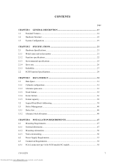
... method, and the defect management. PREFACE This manual describes the MBA3300NC, MBA3300NP, MBA3147NC, MBA3147NP, MBA3073NC, and MBA3073NP 3.5-inch SCSI hard disk drives. This manual is written for error analysis and how analyze collected error information. CHAPTER 2 SPECIFICATIONS This...This chapter describes the automatic diagnosis and maintenance of interface connector. C141-E270 1 Downloaded from www.Manualslib.com manuals search engine CHAPTER 5 INSTALLATION This chapter explains how to install the disk drives. APPENDIX A TO B The appendixes give supplementary information, ...
... method, and the defect management. PREFACE This manual describes the MBA3300NC, MBA3300NP, MBA3147NC, MBA3147NP, MBA3073NC, and MBA3073NP 3.5-inch SCSI hard disk drives. This manual is written for error analysis and how analyze collected error information. CHAPTER 2 SPECIFICATIONS This...This chapter describes the automatic diagnosis and maintenance of interface connector. C141-E270 1 Downloaded from www.Manualslib.com manuals search engine CHAPTER 5 INSTALLATION This chapter explains how to install the disk drives. APPENDIX A TO B The appendixes give supplementary information, ...
Product Manual
Page 7
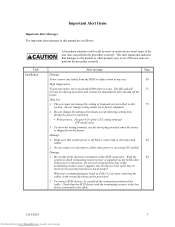
... off the power. The DE and LSI 71 become hot during the power is turned on. • Write protect: Pin pair 9/10 of the SCSI connectors. Damage 1. When the recommended parts listed in Table 4.2 are as follows: Task Installation A hazardous situation could result in the wrong direction can be prevented. 2. Alert...
... off the power. The DE and LSI 71 become hot during the power is turned on. • Write protect: Pin pair 9/10 of the SCSI connectors. Damage 1. When the recommended parts listed in Table 4.2 are as follows: Task Installation A hazardous situation could result in the wrong direction can be prevented. 2. Alert...
Product Manual
Page 8
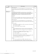
Fujitsu 99 does not assume responsibility if data is hot. Electrical shock 100 - Never touch the HDDs while power-feeding. Damage - Never remove a PCBA. - Damage - diagnostics. To avoid shocks, turn the power off the power. Connect the ribbon cable to a cable connector with a colored ... the HDD while it is corrupted during operation and remain hot immediately after turning off the power before connecting or disconnecting a cable, connector, or plug. - ESD (Electrostatics Discharge) may cause the damage to clean the HDDs. - To prevent electrical damage to other ...
Fujitsu 99 does not assume responsibility if data is hot. Electrical shock 100 - Never touch the HDDs while power-feeding. Damage - Never remove a PCBA. - Damage - diagnostics. To avoid shocks, turn the power off the power. Connect the ribbon cable to a cable connector with a colored ... the HDD while it is corrupted during operation and remain hot immediately after turning off the power before connecting or disconnecting a cable, connector, or plug. - ESD (Electrostatics Discharge) may cause the damage to clean the HDDs. - To prevent electrical damage to other ...
Product Manual
Page 11
... CHAPTER 4 INSTALLATION REQUIREMENTS 47 4.1 Mounting Requirements 47 4.1.1 External dimensions ...47 4.1.2 Mounting orientations ...50 4.1.3 Notes on mounting ...50 4.2 Power Supply Requirements 53 4.3 Connection Requirements 58 4.3.1 SCA2 connector type 16-bit SCSI model (NC model 58 C141-E270 7 Downloaded from www.Manualslib.com manuals search engine
... CHAPTER 4 INSTALLATION REQUIREMENTS 47 4.1 Mounting Requirements 47 4.1.1 External dimensions ...47 4.1.2 Mounting orientations ...50 4.1.3 Notes on mounting ...50 4.2 Power Supply Requirements 53 4.3 Connection Requirements 58 4.3.1 SCA2 connector type 16-bit SCSI model (NC model 58 C141-E270 7 Downloaded from www.Manualslib.com manuals search engine
Product Manual
Page 12
... 16-bit SCSI model (NP model 60 Cable connector requirements 67 External operator panel (on NP model drives only 68 CHAPTER 5 INSTALLATION 71 5.1 Notes on Handling HDDs 71 5.2 Connections...73 5.3 Setting Terminals ...75 5.3.1 SCSI ID setting...76 5.3.2 Each mode setting ...78 5.3.3 Mode settings ...80 5.4 Mounting HDDs...81 5.4.1 Check before mounting ...81 5.4.2 Mounting procedures...
... 16-bit SCSI model (NP model 60 Cable connector requirements 67 External operator panel (on NP model drives only 68 CHAPTER 5 INSTALLATION 71 5.1 Notes on Handling HDDs 71 5.2 Connections...73 5.3 Setting Terminals ...75 5.3.1 SCSI ID setting...76 5.3.2 Each mode setting ...78 5.3.3 Mode settings ...80 5.4 Mounting HDDs...81 5.4.1 Check before mounting ...81 5.4.2 Mounting procedures...
Product Manual
Page 13
... (B-4E-00): SCSI interface error 116 APPENDIX A SETTING TERMINALS 117 A.1 Setting Terminals (on NP model only 118 APPENDIX B CONNECTOR SIGNAL ALLOCATION 119 B.1 SCSI Connector Signal Allocation: SCA2 type LVD 16-bit SCSI 120 B.2 SCSI Connector Signal Allocation: 68-pin type LVD 16-bit SCSI 121 GLOSSARY ...123 ACRONYMS AND ABBREVIATIONS 125 INDEX ...127...
... (B-4E-00): SCSI interface error 116 APPENDIX A SETTING TERMINALS 117 A.1 Setting Terminals (on NP model only 118 APPENDIX B CONNECTOR SIGNAL ALLOCATION 119 B.1 SCSI Connector Signal Allocation: SCA2 type LVD 16-bit SCSI 120 B.2 SCSI Connector Signal Allocation: 68-pin type LVD 16-bit SCSI 121 GLOSSARY ...123 ACRONYMS AND ABBREVIATIONS 125 INDEX ...127...

Product Manual
Page 14
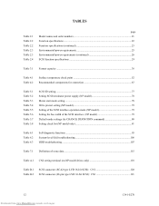
... AC noise filter (recommended 58 NC connectors location ...58 SCA2 type 16-bit SCSI connector 59 NP connectors and terminals location 60 68-pin type 16-bit SCSI interface connector 61 Power supply connector (68-pin type 16-bit SCSI 61 External operator panel connector (CN1 62 External operator panel connector (CN2 62 16-bit SCSI ID...
... AC noise filter (recommended 58 NC connectors location ...58 SCA2 type 16-bit SCSI connector 59 NP connectors and terminals location 60 68-pin type 16-bit SCSI interface connector 61 Power supply connector (68-pin type 16-bit SCSI 61 External operator panel connector (CN1 62 External operator panel connector (CN2 62 16-bit SCSI ID...
Product Manual
Page 16
... troubleshooting 106 HDD troubleshooting ...107 Table 7.1 Definition of sense data ...115 Table A.1 CN2 setting terminal (on NP model drives only 118 Table B.1 Table B.2 SCSI connector (SCA2 type LVD 16-bit SCSI): CN1 120 SCSI connector (68-pin type LVD 16-bit SCSI): CN1 121 12 Downloaded from www.Manualslib.com manuals search engine...
... troubleshooting 106 HDD troubleshooting ...107 Table 7.1 Definition of sense data ...115 Table A.1 CN2 setting terminal (on NP model drives only 118 Table B.1 Table B.2 SCSI connector (SCA2 type LVD 16-bit SCSI): CN1 120 SCSI connector (68-pin type LVD 16-bit SCSI): CN1 121 12 Downloaded from www.Manualslib.com manuals search engine...

Product Manual
Page 25
... Order number SCSI type MBA3300NC MBA3300NP MBA3147NC MBA3147NP MBA3073NC MBA3073NP CA06708-B400 CA06708-B850 CA06708-B200 CA06708-B650 CA06708-B100 CA06708-B550 SCA2, LVD 68-pin, LVD SCA2, LVD 68-pin, LVD SCA2, LVD 68-pin, LVD Capacity (user area) 300 GB (*) 147 GB (*) 73.5 GB (*) (*) One gigabyte (GB) = one billion bytes; CHAPTER 2 SPECIFICATIONS 2.1 Hardware Specifications...
... Order number SCSI type MBA3300NC MBA3300NP MBA3147NC MBA3147NP MBA3073NC MBA3073NP CA06708-B400 CA06708-B850 CA06708-B200 CA06708-B650 CA06708-B100 CA06708-B550 SCA2, LVD 68-pin, LVD SCA2, LVD 68-pin, LVD SCA2, LVD 68-pin, LVD Capacity (user area) 300 GB (*) 147 GB (*) 73.5 GB (*) (*) One gigabyte (GB) = one billion bytes; CHAPTER 2 SPECIFICATIONS 2.1 Hardware Specifications...
Product Manual
Page 30
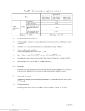
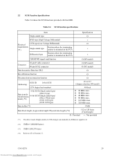
... Peak operating current DC (reference) (*6) Ripple (+5 V, +12 V) MBA3300NC MBA3300NP Specification MBA3147NC MBA3147NP ± 5 % 0.5 A MBA3073NC MBA3073NP 1.5 A 0.79 A 250 mVp-p or less (*7) (*1) For detail condition, see Section 4.1. (*2) Vibration applied to be ...which cannot be less than 2.5 mm. (*5) Input voltages are specified at the HDD connector side during HDD Idle state. (*6) Operating currents are values under random W/R operation of... assignments are not included in the error rate. Data blocks to the drive is measured at near the mounting screw hole on retry setting with log...
... Peak operating current DC (reference) (*6) Ripple (+5 V, +12 V) MBA3300NC MBA3300NP Specification MBA3147NC MBA3147NP ± 5 % 0.5 A MBA3073NC MBA3073NP 1.5 A 0.79 A 250 mVp-p or less (*7) (*1) For detail condition, see Section 4.1. (*2) Vibration applied to be ...which cannot be less than 2.5 mm. (*5) Input voltages are specified at the HDD connector side during HDD Idle state. (*6) Operating currents are values under random W/R operation of... assignments are not included in the error rate. Data blocks to the drive is measured at near the mounting screw hole on retry setting with log...
Product Manual
Page 33
... PCA × Differential type Position where the terminating resistor is mounted on the PCA × TERMPWR signal send function Ο (NP model) Connector 68-pin P cable connector 80-pin SCA2 connector Ο (NP model) Ο (NC model) Data bus parity (Data bus CRC) Ο Bus arbitration function Ο Disconnection/reconnection function Ο Addressing...
... PCA × Differential type Position where the terminating resistor is mounted on the PCA × TERMPWR signal send function Ο (NP model) Connector 68-pin P cable connector 80-pin SCA2 connector Ο (NP model) Ο (NC model) Data bus parity (Data bus CRC) Ο Bus arbitration function Ο Disconnection/reconnection function Ο Addressing...

Product Manual
Page 57
... that the leakage magnetic flux influence easily. 4.2 Power Supply Requirements (1) Allowable input voltage and current The power supply input voltage measured at the power supply connector pin of the HDD (receiving end) must satisfy the requirement given in Subsection 2.1.3. (For other requirements, see Items (4) and (5) below.) (2) Current waveform (reference) Figure 4.7 shows...
... that the leakage magnetic flux influence easily. 4.2 Power Supply Requirements (1) Allowable input voltage and current The power supply input voltage measured at the power supply connector pin of the HDD (receiving end) must satisfy the requirement given in Subsection 2.1.3. (For other requirements, see Items (4) and (5) below.) (2) Current waveform (reference) Figure 4.7 shows...

Product Manual
Page 62
SCSI connector (CN1) (including power supply) Figure 4.13 NC connectors location 58 Downloaded from www.Manualslib.com manuals search engine C141-E270 Figure 4.12 AC noise filter (recommended) 4.3 Connection Requirements 4.3.1 SCA2 connector type 16-bit SCSI model (NC model) (1) Connectors Figure 4.13 shows the locations of connectors on the SCA2 connector type 16-bit SCSI model (NC model).
SCSI connector (CN1) (including power supply) Figure 4.13 NC connectors location 58 Downloaded from www.Manualslib.com manuals search engine C141-E270 Figure 4.12 AC noise filter (recommended) 4.3 Connection Requirements 4.3.1 SCA2 connector type 16-bit SCSI model (NC model) (1) Connectors Figure 4.13 shows the locations of connectors on the SCA2 connector type 16-bit SCSI model (NC model).

Product Manual
Page 63
...-E270 59 Downloaded from www.Manualslib.com manuals search engine Figure 4.14 SCA2 type 16-bit SCSI connector (3) Connector for external operator panel This connector is included in Appendix B for NC model drives. The power connector is not available for signal assignments on the physical/electrical requirements of the interface signals, refer to SCSI-3 type...
...-E270 59 Downloaded from www.Manualslib.com manuals search engine Figure 4.14 SCA2 type 16-bit SCSI connector (3) Connector for external operator panel This connector is included in Appendix B for NC model drives. The power connector is not available for signal assignments on the physical/electrical requirements of the interface signals, refer to SCSI-3 type...

Product Manual
Page 64
... (NP model). • Power supply connector • SCSI connector • External operator panel connector External operator panel connector (CN2) Power supply connector (CN1) External operator panel connector (CN1) SCSI connector (CN1) Figure 4.15 NP connectors and terminals location (2) SCSI connector and power supply connector a. 16-bit SCSI The connector for the signal assignments on the SCSI connector. Figure 4.16 shows the SCSI...
... (NP model). • Power supply connector • SCSI connector • External operator panel connector External operator panel connector (CN2) Power supply connector (CN1) External operator panel connector (CN1) SCSI connector (CN1) Figure 4.15 NP connectors and terminals location (2) SCSI connector and power supply connector a. 16-bit SCSI The connector for the signal assignments on the SCSI connector. Figure 4.16 shows the SCSI...

Product Manual
Page 65
... ID setting switch. This allows connection of an external LED on the power supply side. (4) Connector for external operator panel • Connector for 16-bit SCSI external operator panel CN1 provides connector for the external operator panel other than the SCSI bus as shown in Figure 4.18. Power ...external operator panel are provided on the HDD as shown in Figure 4.19. C141-E270 61 Downloaded from www.Manualslib.com manuals search engine Also, a connector for DC grounding. Pin 34 Pin 1 2.00mm Pin A1 Pin 1 2.54mm Pin 68 1.27mm Pin 35 2.00m Pin A2 5.08mm 0.40mm 0.635mm...
... ID setting switch. This allows connection of an external LED on the power supply side. (4) Connector for external operator panel • Connector for 16-bit SCSI external operator panel CN1 provides connector for the external operator panel other than the SCSI bus as shown in Figure 4.18. Power ...external operator panel are provided on the HDD as shown in Figure 4.19. C141-E270 61 Downloaded from www.Manualslib.com manuals search engine Also, a connector for DC grounding. Pin 34 Pin 1 2.00mm Pin A1 Pin 1 2.54mm Pin 68 1.27mm Pin 35 2.00m Pin A2 5.08mm 0.40mm 0.635mm...

Product Manual
Page 67
Figure 4.20 shows the electrical requirements. Figure 4.20 16-bit SCSI ID external input C141-E270 63 Downloaded from www.Manualslib.com manuals search engine (5) External operator panel connector Signals a. 16-bit SCSI -ID3, -ID2, -ID1, -ID0: Input signals (CN1-A1, A3, A5, A7 pin and CN2-02, 04, 06, 08 pin) These signals are used for providing switches to set the SCSI ID of the HDD externally. For the recommended circuit examples, see Subsection 4.3.4.
Figure 4.20 shows the electrical requirements. Figure 4.20 16-bit SCSI ID external input C141-E270 63 Downloaded from www.Manualslib.com manuals search engine (5) External operator panel connector Signals a. 16-bit SCSI -ID3, -ID2, -ID1, -ID0: Input signals (CN1-A1, A3, A5, A7 pin and CN2-02, 04, 06, 08 pin) These signals are used for providing switches to set the SCSI ID of the HDD externally. For the recommended circuit examples, see Subsection 4.3.4.

Product Manual
Page 71
... lists the recommended components cable connection. Table 4.2 Recommended components for connection Applicable model Type Name NC SCSI connector (CN1) Connector Part number (Size) 787311-4 71743-1085 Manufacturer Tyco Electronics AMP Reference (*1) Molex Cable socket DHJ-PAC68-...(CN1) Contact A3B-2630SCC HIROSE ELECTRIC S3 Cable (AWG26 to 36) Cable socket housing FCN-723J024/2M FUJITSU TAKAMIZAWA External operator panel (CN2) Contact FCN-723J-G/AM FUJITSU TAKAMIZAWA S4 Cable (AWG28) (*1) See Figure 4.22. (1) SCSI cable Refer to Section 1.3 "Physical Requirements...
... lists the recommended components cable connection. Table 4.2 Recommended components for connection Applicable model Type Name NC SCSI connector (CN1) Connector Part number (Size) 787311-4 71743-1085 Manufacturer Tyco Electronics AMP Reference (*1) Molex Cable socket DHJ-PAC68-...(CN1) Contact A3B-2630SCC HIROSE ELECTRIC S3 Cable (AWG26 to 36) Cable socket housing FCN-723J024/2M FUJITSU TAKAMIZAWA External operator panel (CN2) Contact FCN-723J-G/AM FUJITSU TAKAMIZAWA S4 Cable (AWG28) (*1) See Figure 4.22. (1) SCSI cable Refer to Section 1.3 "Physical Requirements...

Product Manual
Page 72
...Ω (*1) C N 2 S4 21 LED (+5V) 22 -LED (for the system. When connection is not required, leave open the following pins in the external operator panel connector of the HDD: Pins 21, 22 and pins 01 through 08 in CN2 and pins A1 through A12 in CN1. 4.3.4 External operator panel (on NP...
...Ω (*1) C N 2 S4 21 LED (+5V) 22 -LED (for the system. When connection is not required, leave open the following pins in the external operator panel connector of the HDD: Pins 21, 22 and pins 01 through 08 in CN2 and pins A1 through A12 in CN1. 4.3.4 External operator panel (on NP...
Product Manual
Page 76
...reason. (3) Installation/removal/replacement a) Do not attempt to connect or disconnect connections when power is recommended to the PCBA and interface connector when removing the HDD from the HDD. d) Keep a record of the mount allowable directions in temperature. 72 Downloaded from direct ...package with cushions. Handle the package on soft material such as a wooden desk. Never open the DE for storage. b) It is on hard material such as a rubber mat, not on . c) To prevent condensation, avoid sudden changes in Subsection 4.2.2. (6) Storage a) Provide moistureproof packaging...
...reason. (3) Installation/removal/replacement a) Do not attempt to connect or disconnect connections when power is recommended to the PCBA and interface connector when removing the HDD from the HDD. d) Keep a record of the mount allowable directions in temperature. 72 Downloaded from direct ...package with cushions. Handle the package on soft material such as a wooden desk. Never open the DE for storage. b) It is on hard material such as a rubber mat, not on . c) To prevent condensation, avoid sudden changes in Subsection 4.2.2. (6) Storage a) Provide moistureproof packaging...