Product Manual
Page 11
CONTENTS page CHAPTER 1 GENERAL DESCRIPTION 13 1.1 Standard Features ...14 1.2 Hardware Structure ...18 1.3 System Configuration...19 CHAPTER 2 SPECIFICATIONS 21 2.1 Hardware Specifications 21 2.1.1 Model name and order number 21 2.1.2 Function specifications...22 2.1.3 Environmental ...
CONTENTS page CHAPTER 1 GENERAL DESCRIPTION 13 1.1 Standard Features ...14 1.2 Hardware Structure ...18 1.3 System Configuration...19 CHAPTER 2 SPECIFICATIONS 21 2.1 Hardware Specifications 21 2.1.1 Model name and order number 21 2.1.2 Function specifications...22 2.1.3 Environmental ...

Product Manual
Page 14
... 42 Alternate block allocation by REASSIGN BLOCKS command 43 Figure 4.1 Figure 4.2 Figure 4.3 Figure 4.4 Figure 4.5 Figure 4.6 Figure 4.7 Figure 4.8 Figure 4.9 Figure 4.10 Figure 4.11 Figure 4.12 Figure 4.13 Figure 4.14 Figure 4.15 Figure 4.16 Figure 4.17 Figure 4.18 Figure 4.19 Figure 4.20 Figure 4.21 Figure 4.22 NC model dimensions...48 NP model dimensions...
... 42 Alternate block allocation by REASSIGN BLOCKS command 43 Figure 4.1 Figure 4.2 Figure 4.3 Figure 4.4 Figure 4.5 Figure 4.6 Figure 4.7 Figure 4.8 Figure 4.9 Figure 4.10 Figure 4.11 Figure 4.12 Figure 4.13 Figure 4.14 Figure 4.15 Figure 4.16 Figure 4.17 Figure 4.18 Figure 4.19 Figure 4.20 Figure 4.21 Figure 4.22 NC model dimensions...48 NP model dimensions...

Product Manual
Page 17
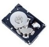
...com manuals search engine The HDDs support the Small Computer System Interface (SCSI) as the powerful command set of the MBA3xxxxx. C141-E270 13 Downloaded from the format at factory shipment by reinitializing with an embedded SCSI controller. The flexibility and expandability of the SCSI, as well... as described in this manual. The HDDs are high performance large capacity 3.5-inch hard disk drives with the user's system. Refer to the extent described in the ANSI SCSI SPI-4 [T10/1365D Rev.10] to Chapter 6 "Disk Media...
...com manuals search engine The HDDs support the Small Computer System Interface (SCSI) as the powerful command set of the MBA3xxxxx. C141-E270 13 Downloaded from the format at factory shipment by reinitializing with an embedded SCSI controller. The flexibility and expandability of the SCSI, as well... as described in this manual. The HDDs are high performance large capacity 3.5-inch hard disk drives with the user's system. Refer to the extent described in the ANSI SCSI SPI-4 [T10/1365D Rev.10] to Chapter 6 "Disk Media...

Product Manual
Page 20
... Command queuing feature The HDD can queue maximum 128 commands, and optimizes the issuing order of queued commands by using its alternate data block. (13) Programmable data block length Data can automatically reassign its powerful retry processing. To ensure it, you turn off the HDD's power. The initiator ...a multiple of four within the range of 512 to 528 bytes. The Recoverable Error of the drive might increase when the format would be specified at factory shipment is sense data (1-13-xx). 16 Downloaded from 512 bytes to the initiator after being corrected in the multi-host or...
... Command queuing feature The HDD can queue maximum 128 commands, and optimizes the issuing order of queued commands by using its alternate data block. (13) Programmable data block length Data can automatically reassign its powerful retry processing. To ensure it, you turn off the HDD's power. The initiator ...a multiple of four within the range of 512 to 528 bytes. The Recoverable Error of the drive might increase when the format would be specified at factory shipment is sense data (1-13-xx). 16 Downloaded from 512 bytes to the initiator after being corrected in the multi-host or...

Product Manual
Page 26
... time 30 s typ. (60 s max.) 30 s typ. Power consumption (*5) 13.06 W typ. Table 2.2 Function specifications Specification Item MBA3300NC MBA3147NC MBA3073NC MBA3300NP MBA3147NP MBA3073NP Format capacity (*1) Number of disks Number of the HDD. 2.1.2 Function specifications Table 2.2 shows the function specifications of heads 300 GB (*2) 4 8 147 GB (*2) 2 4 73.5 GB (*2) 1 2 Tracks per Surface 82,604 cyl typ. (standard format...
... time 30 s typ. (60 s max.) 30 s typ. Power consumption (*5) 13.06 W typ. Table 2.2 Function specifications Specification Item MBA3300NC MBA3147NC MBA3073NC MBA3300NP MBA3147NP MBA3073NP Format capacity (*1) Number of disks Number of the HDD. 2.1.2 Function specifications Table 2.2 shows the function specifications of heads 300 GB (*2) 4 8 147 GB (*2) 2 4 73.5 GB (*2) 1 2 Tracks per Surface 82,604 cyl typ. (standard format...

Product Manual
Page 28
(*10) The maximum data transfer rate may be restricted to the response speed of initiator and by transmission characteristics. 1MB/s=1,000,000 bytes/s. (*11) Refer to 1.1(13). (*12) 1MB=1,048,576 bytes 24 Downloaded from www.Manualslib.com manuals search engine C141-E270
(*10) The maximum data transfer rate may be restricted to the response speed of initiator and by transmission characteristics. 1MB/s=1,000,000 bytes/s. (*11) Refer to 1.1(13). (*12) 1MB=1,048,576 bytes 24 Downloaded from www.Manualslib.com manuals search engine C141-E270
Product Manual
Page 33
... (Single-ended type) Data transfer (Synchronous mode) (*2) (Ultra 2 type) 16-bit SCSI (Single-ended type) (Ultra 2 Wide type) (U160 LVD type) (U320 LVD type) #0 to (13) of Section 1.1. 2.2 SCSI Function Specifications Table 2.4 shows the SCSI functions provided with the HDD. Data buffer (*3) 8 MB Data block length (Logical data length=Physical data...
... (Single-ended type) Data transfer (Synchronous mode) (*2) (Ultra 2 type) 16-bit SCSI (Single-ended type) (Ultra 2 Wide type) (U160 LVD type) (U320 LVD type) #0 to (13) of Section 1.1. 2.2 SCSI Function Specifications Table 2.4 shows the SCSI functions provided with the HDD. Data buffer (*3) 8 MB Data block length (Logical data length=Physical data...

Product Manual
Page 62
Figure 4.12 AC noise filter (recommended) 4.3 Connection Requirements 4.3.1 SCA2 connector type 16-bit SCSI model (NC model) (1) Connectors Figure 4.13 shows the locations of connectors on the SCA2 connector type 16-bit SCSI model (NC model). SCSI connector (CN1) (including power supply) Figure 4.13 NC connectors location 58 Downloaded from www.Manualslib.com manuals search engine C141-E270
Figure 4.12 AC noise filter (recommended) 4.3 Connection Requirements 4.3.1 SCA2 connector type 16-bit SCSI model (NC model) (1) Connectors Figure 4.13 shows the locations of connectors on the SCA2 connector type 16-bit SCSI model (NC model). SCSI connector (CN1) (including power supply) Figure 4.13 NC connectors location 58 Downloaded from www.Manualslib.com manuals search engine C141-E270

Product Manual
Page 79
Do not change the setting of the CN2 setting terminal (NP model only) 3. See Figure 4.13 and Table B for NP model. Pin 2 CN2 Pin 24 Pin 1 Pin 23 Figure 5.2 Setting terminals location (on . • Write protect: Pin pair 9/10 of terminals ...
Do not change the setting of the CN2 setting terminal (NP model only) 3. See Figure 4.13 and Table B for NP model. Pin 2 CN2 Pin 24 Pin 1 Pin 23 Figure 5.2 Setting terminals location (on . • Write protect: Pin pair 9/10 of terminals ...

Product Manual
Page 80
... is set using the external operator panel connector CN1 of NP model, all pins listed in Table 5.1 should be open. For NP model, see Figure 4.13 and Table B.1. Force Single Ended: LVD mode Force Narrow: 16-bit SCSI Motor start mode Write protect: enabled SCSI ID #15 Figure 5.3 CN2 setting terminal... (on NP models only) 5.3.1 SCSI ID setting Table 5.1 shows the SCSI ID setting. 2 4 6 8 10 12 14 16 18 20 22 24 1 3 5 7 9 11 13 15 17 19 21 23 Terminator power supply: Supply (LED signal) (HDD Reset signal) N.C.
... is set using the external operator panel connector CN1 of NP model, all pins listed in Table 5.1 should be open. For NP model, see Figure 4.13 and Table B.1. Force Single Ended: LVD mode Force Narrow: 16-bit SCSI Motor start mode Write protect: enabled SCSI ID #15 Figure 5.3 CN2 setting terminal... (on NP models only) 5.3.1 SCSI ID setting Table 5.1 shows the SCSI ID setting. 2 4 6 8 10 12 14 16 18 20 22 24 1 3 5 7 9 11 13 15 17 19 21 23 Terminator power supply: Supply (LED signal) (HDD Reset signal) N.C.

Product Manual
Page 81
... the same SCSI bus. 3. The priority of SCSI bus use in ARBITRATION phase is determined by SCSI ID as follows: 7 > 6 > 5 > 4 > 3 > 2 > 1 > 0 > 15 > 14 > 13 > 12 > 11 > 10 > 9 > 8 C141-E270 77 Downloaded from an external source. 2. IMPORTANT 1. Table 5.1 SCSI ID setting SCSI ID 0 1 2 3 4 5 6 7 8 9 10 11 12... 13 14 15 (*1) Pin 39 Open Short Open Short Open Short Open Short Open Short Open Short Open Short Open Short NC model (CN1) Pin 79 ...
... the same SCSI bus. 3. The priority of SCSI bus use in ARBITRATION phase is determined by SCSI ID as follows: 7 > 6 > 5 > 4 > 3 > 2 > 1 > 0 > 15 > 14 > 13 > 12 > 11 > 10 > 9 > 8 C141-E270 77 Downloaded from an external source. 2. IMPORTANT 1. Table 5.1 SCSI ID setting SCSI ID 0 1 2 3 4 5 6 7 8 9 10 11 12... 13 14 15 (*1) Pin 39 Open Short Open Short Open Short Open Short Open Short Open Short Open Short Open Short NC model (CN1) Pin 79 ...

Product Manual
Page 83
... NC model, the function of the write protect setting is not supported. (4) Setting of the SCSI interface operation mode By establishing a short-circuit between CN2-13 and CN2-14 on the SCSI bus Single-Ended mode *1. Table 5.6 Setting the bus width of the SCSI interface's upper bus (DB8-15, P1) inside... the HDD only when the top-level bus (DB8-15, P1) for the SCSI interface is not supported. Set at factory shipment. Pin pair 13/14 of CN2 (GND/8/16 SW) Open (*1) Short For NC model, the function of the bus width setting for the HDD SCSI interface is not...
... NC model, the function of the write protect setting is not supported. (4) Setting of the SCSI interface operation mode By establishing a short-circuit between CN2-13 and CN2-14 on the SCSI bus Single-Ended mode *1. Table 5.6 Setting the bus width of the SCSI interface's upper bus (DB8-15, P1) inside... the HDD only when the top-level bus (DB8-15, P1) for the SCSI interface is not supported. Set at factory shipment. Pin pair 13/14 of CN2 (GND/8/16 SW) Open (*1) Short For NC model, the function of the bus width setting for the HDD SCSI interface is not...

Product Manual
Page 85
...(Check item) 1 SCSI ID 2 Write protect 3 Motor start mode 4 Force Narrow 5 Force single ended 6 Terminator power supply Pin pair on CN2 1/2 3/4 5/6 7/8 9/10 11/12 13/14 15/16 23/24 Check … (SCSI ID = __) Remarks Upper bus (DB 8 to 15 PI) not connected … Short … Short … Short.... 3) Confirm the DE is not touching the frame on the system cabinet, connect the external operator panel cable before mounting the NP model drives in the system cabinet. For the CN2 setting terminal location, see Figure 4.4). • When mounting the HDD, be careful not to each system.
...(Check item) 1 SCSI ID 2 Write protect 3 Motor start mode 4 Force Narrow 5 Force single ended 6 Terminator power supply Pin pair on CN2 1/2 3/4 5/6 7/8 9/10 11/12 13/14 15/16 23/24 Check … (SCSI ID = __) Remarks Upper bus (DB 8 to 15 PI) not connected … Short … Short … Short.... 3) Confirm the DE is not touching the frame on the system cabinet, connect the external operator panel cable before mounting the NP model drives in the system cabinet. For the CN2 setting terminal location, see Figure 4.4). • When mounting the HDD, be careful not to each system.

Product Manual
Page 122
... 13 - 14 15 - 16 23 - 24 Setting contents Motor start mode Open Started by the START/STOP command Short Started by turning the power supply on (*) Force Narrow Open Width of 16-bit bus (*) Short Width of 8-bit bus Force Single Ended Open Follows DIFFSNS signal level on NP model drives only...) Short Open Short SCSI ID #11 (16-bit SCSI only) Open Short Short SCSI ID #12 (16-bit SCSI only) Open Short Short SCSI ID #13 (16-bit SCSI only) Short Short Short SCSI ID #14 (16-bit SCSI only) Short Short Short SCSI ID #15 (16-bit SCSI only) (*) Open...
... 13 - 14 15 - 16 23 - 24 Setting contents Motor start mode Open Started by the START/STOP command Short Started by turning the power supply on (*) Force Narrow Open Width of 16-bit bus (*) Short Width of 8-bit bus Force Single Ended Open Follows DIFFSNS signal level on NP model drives only...) Short Open Short SCSI ID #11 (16-bit SCSI only) Open Short Short SCSI ID #12 (16-bit SCSI only) Open Short Short SCSI ID #13 (16-bit SCSI only) Short Short Short SCSI ID #14 (16-bit SCSI only) Short Short Short SCSI ID #15 (16-bit SCSI only) (*) Open...

Product Manual
Page 124
... (Charge) N. B.1 SCSI Connector Signal Allocation: SCA2 type LVD 16-bit SCSI Pin No. 01 02 03 04 05 06 07 08 09 10 11 12 13 14 15 16 17 18 19 20 21 22 23 24 25 26 27 28 29 30 31 32 33 34 35 36 37 38... 48 49 50 51 52 53 54 55 56 57 58 59 60 61 62 63 64 65 66 67 68 69 70 71 72 73 74 75 76 77 78 79 80 120 Downloaded from www.Manualslib.com manuals search engine C141-E270 C.
... (Charge) N. B.1 SCSI Connector Signal Allocation: SCA2 type LVD 16-bit SCSI Pin No. 01 02 03 04 05 06 07 08 09 10 11 12 13 14 15 16 17 18 19 20 21 22 23 24 25 26 27 28 29 30 31 32 33 34 35 36 37 38... 48 49 50 51 52 53 54 55 56 57 58 59 60 61 62 63 64 65 66 67 68 69 70 71 72 73 74 75 76 77 78 79 80 120 Downloaded from www.Manualslib.com manuals search engine C141-E270 C.

Product Manual
Page 125
.... Signal 01 DB12 02 DB13 03 DB14 04 DB15 05 DBP1 06 DB00 07 DB01 08 DB02 09 DB03 10 DB04 11 DB05 12 DB06 13 DB07 14 P_CRCA 15 GND 16 DIFFSNS 17 TERMPWR* 18 TERMPWR* 19 (Reserved) 20 GND 21 ATN 22 GND 23 BSY 24 ACK 25 RST...
.... Signal 01 DB12 02 DB13 03 DB14 04 DB15 05 DBP1 06 DB00 07 DB01 08 DB02 09 DB03 10 DB04 11 DB05 12 DB06 13 DB07 14 P_CRCA 15 GND 16 DIFFSNS 17 TERMPWR* 18 TERMPWR* 19 (Reserved) 20 GND 21 ATN 22 GND 23 BSY 24 ACK 25 RST...