Manual/User Guide
Page 9
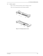
Table 4.2 lists the signal allocation of the SAS plug on the HDD. S1 S7 P1 P15 S14 S8 Figure 4.10 SAS plug connector overview C141-E219 4-9 4.3 Connection Requirements 4.3.2 Interface connector Figure 4.10 shows the SAS type interface connector (SAS plug) overview.
Table 4.2 lists the signal allocation of the SAS plug on the HDD. S1 S7 P1 P15 S14 S8 Figure 4.10 SAS plug connector overview C141-E219 4-9 4.3 Connection Requirements 4.3.2 Interface connector Figure 4.10 shows the SAS type interface connector (SAS plug) overview.
Manual/User Guide
Page 10
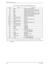
...) signal allocation:CN1 Pin No. S14 are 3.3V power supply input and pre-charge signals, and not used on MAV2073RC and MAV2036RC. Note 2) P1 to P3 are SAS Secondary Port signals, and not used GROUND GROUND GROUND Pre-charge pin for +5V +5V power supply input +5V power supply input GROUND READY... LED output GROUND Pre-charge pin for SAS Secondary Port Not used Not used Not used on MAV2073RC and MAV2036RC. 4-10 C141-E219 S1 S2 S3 S4 S5 S6 S7 S8 Note1 S9 Note1 S10 Note1 S11 Note1 S12 Note1...
...) signal allocation:CN1 Pin No. S14 are 3.3V power supply input and pre-charge signals, and not used on MAV2073RC and MAV2036RC. Note 2) P1 to P3 are SAS Secondary Port signals, and not used GROUND GROUND GROUND Pre-charge pin for +5V +5V power supply input +5V power supply input GROUND READY... LED output GROUND Pre-charge pin for SAS Secondary Port Not used Not used Not used on MAV2073RC and MAV2036RC. 4-10 C141-E219 S1 S2 S3 S4 S5 S6 S7 S8 Note1 S9 Note1 S10 Note1 S11 Note1 S12 Note1...