Product Manual
Page 5
... Standard for American National Information Systems-Small Computer Standards Institute System Interface (SCSI) (ANSI) American National Standard for Information Systems-SCSI-3 Fast-20 Parallel Interface (Fast 20-SCSI) American National Standards Institute (ANSI) All Right Reserved, Copyright © 1997, 1998 Fujitsu Limited iv C141-E035-03EN Related Standards Specifications and functions of the Small...
... Standard for American National Information Systems-Small Computer Standards Institute System Interface (SCSI) (ANSI) American National Standard for Information Systems-SCSI-3 Fast-20 Parallel Interface (Fast 20-SCSI) American National Standards Institute (ANSI) All Right Reserved, Copyright © 1997, 1998 Fujitsu Limited iv C141-E035-03EN Related Standards Specifications and functions of the Small...
Product Manual
Page 6
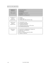
... their standard features, hardware, and system configuration. Chapter 6 DIAGNOSIS and MAINTENANCE This chapter describes the automatic diagnosis, and maintenance of the SCSI interface between host system and disk drive, the data formatted at the factory and device type. APPENDIX A to E The appendixes give supplementary information, including the locations of mounting setting terminals...
... their standard features, hardware, and system configuration. Chapter 6 DIAGNOSIS and MAINTENANCE This chapter describes the automatic diagnosis, and maintenance of the SCSI interface between host system and disk drive, the data formatted at the factory and device type. APPENDIX A to E The appendixes give supplementary information, including the locations of mounting setting terminals...
Product Manual
Page 8
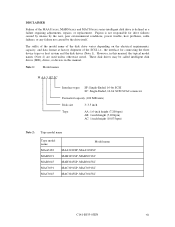
..., MAA3182SC MAB3091SP, MAB3091SC MAB3045SP, MAB3045SC MAC3091SP, MAC3091SC MAC3045SP, MAC3045SC C141-E035-03EN vii However, in this manual, the typical model names (Note 2) are used unless otherwise noted. DISCLAIMER Failure of the SCSI, i.e., the interface for drive failures caused by misuse... and MAC30xxxx series intelligent disk drive is not responsible for connecting the three device types or host system and the disk drives (Note 1). These disk drives may be called intelligent disk drives (IDD), drives, or devices in this manual. Fujitsu is defined as a failure requiring...
..., MAA3182SC MAB3091SP, MAB3091SC MAB3045SP, MAB3045SC MAC3091SP, MAC3091SC MAC3045SP, MAC3045SC C141-E035-03EN vii However, in this manual, the typical model names (Note 2) are used unless otherwise noted. DISCLAIMER Failure of the SCSI, i.e., the interface for drive failures caused by misuse... and MAC30xxxx series intelligent disk drive is not responsible for connecting the three device types or host system and the disk drives (Note 1). These disk drives may be called intelligent disk drives (IDD), drives, or devices in this manual. Fujitsu is defined as a failure requiring...
Product Manual
Page 9
... 2. Specifications and Equipment Configuration 2. Installation Requirements 5. Diagnostics and Maintenance 1. Error Analysis 4. MANUAL ORGANIZATION PRODUCT MANUAL (This manual) SCSI Physical Interface Specifications SCSI Logical Interface Specifications Maintenance Manual 1. Data Buffer Management 3. Removal and Replacement Procedures 5. SCSI Message 3. Command Specification 4. Maintenance and Diagnostic 3. Sense Data and error Recovery Procedure 5. Principle of Operation viii C141-E035...
... 2. Specifications and Equipment Configuration 2. Installation Requirements 5. Diagnostics and Maintenance 1. Error Analysis 4. MANUAL ORGANIZATION PRODUCT MANUAL (This manual) SCSI Physical Interface Specifications SCSI Logical Interface Specifications Maintenance Manual 1. Data Buffer Management 3. Removal and Replacement Procedures 5. SCSI Message 3. Command Specification 4. Maintenance and Diagnostic 3. Sense Data and error Recovery Procedure 5. Principle of Operation viii C141-E035...

Product Manual
Page 10
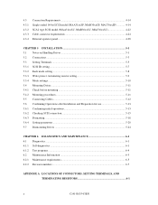
... Standard Features ...1-2 1.2 Hardware Structure...1-5 1.3 System Configuration...1-10 CHAPTER 2 SPECIFICATIONS 2-1 2.1 Hardware Specifications 2-1 2.1.1 Model name and part number 2-1 2.1.2 Function specifications 2-2 2.1.3 Environmental specifications 2-4 2.1.4 Error rate...2-5 2.1.5 Reliability ...2-5 2.2 SCSI Function Specifications 2-7 CHAPTER 3 DATA FORMAT 3-1 3.1 Data Space...3-1 3.1.1 Cylinder configuration...3-1 3.1.2 Alternate spare area ...3-5 3.1.3 Track format ...3-6 3.1.4 Sector format ...3-8 3.1.5 Format capacity ...3-10 3.2 Logical Data Block Addressing 3-11 3.3 Defect...
... Standard Features ...1-2 1.2 Hardware Structure...1-5 1.3 System Configuration...1-10 CHAPTER 2 SPECIFICATIONS 2-1 2.1 Hardware Specifications 2-1 2.1.1 Model name and part number 2-1 2.1.2 Function specifications 2-2 2.1.3 Environmental specifications 2-4 2.1.4 Error rate...2-5 2.1.5 Reliability ...2-5 2.2 SCSI Function Specifications 2-7 CHAPTER 3 DATA FORMAT 3-1 3.1 Data Space...3-1 3.1.1 Cylinder configuration...3-1 3.1.2 Alternate spare area ...3-5 3.1.3 Track format ...3-6 3.1.4 Sector format ...3-8 3.1.5 Format capacity ...3-10 3.2 Logical Data Block Addressing 3-11 3.3 Defect...
Product Manual
Page 11
... 5-11 5.4.2 Mounting procedures...5-11 5.5 Connecting Cables...5-12 5.6 Confirming Operations after Installation and Preparation for use 5-13 5.6.1 Confirming initial operations 5-13 5.6.2 Checking SCSI connection 5-15 5.6.3 Formatting ...5-18 5.6.4 Setting parameters ...5-20 5.7 Dismounting Drives ...5-24 CHAPTER 6 DIAGNOSTICS AND MAINTENANCE 6-1 6.1 Diagnostics ...6-1 6.1.1 Self-diagnostics ...6-1 6.1.2 Test programs ...6-4 6.2 Maintenance Information 6-5 6.2.1 Maintenance requirements 6-5 6.2.2 Revision numbers...6-7 APPENDIX A LOCATIONS OF CONNECTORS, SETTING...
... 5-11 5.4.2 Mounting procedures...5-11 5.5 Connecting Cables...5-12 5.6 Confirming Operations after Installation and Preparation for use 5-13 5.6.1 Confirming initial operations 5-13 5.6.2 Checking SCSI connection 5-15 5.6.3 Formatting ...5-18 5.6.4 Setting parameters ...5-20 5.7 Dismounting Drives ...5-24 CHAPTER 6 DIAGNOSTICS AND MAINTENANCE 6-1 6.1 Diagnostics ...6-1 6.1.1 Self-diagnostics ...6-1 6.1.2 Test programs ...6-4 6.2 Maintenance Information 6-5 6.2.1 Maintenance requirements 6-5 6.2.2 Revision numbers...6-7 APPENDIX A LOCATIONS OF CONNECTORS, SETTING...

Product Manual
Page 12
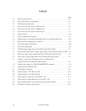
... TERMINALS B-1 B.1 Setting Terminals (MAx3xxxSP: Single-ended 16-bit SCSI B-2 APPENDIX C CONNECTOR SIGNAL ALLOCATION C-1 C.1 SCSI Connector Signal Allocation: SCA2 type 16-bit SCSI C-2 C.2 SCSI Connector Signal Allocation: Single-ended type 16-bit SCSI C-3 APPENDIX D MODEL NAMES AND PRODUCT NUMBERS D-1 D.1 Model Names and Product Numbers D-2 APPENDIX E SCSI INTERFACE FUNCTIONS E-1 E.1 SCSI interface function specifications E-2 Index...IN-1 C141-E035-03EN xi
... TERMINALS B-1 B.1 Setting Terminals (MAx3xxxSP: Single-ended 16-bit SCSI B-2 APPENDIX C CONNECTOR SIGNAL ALLOCATION C-1 C.1 SCSI Connector Signal Allocation: SCA2 type 16-bit SCSI C-2 C.2 SCSI Connector Signal Allocation: Single-ended type 16-bit SCSI C-3 APPENDIX D MODEL NAMES AND PRODUCT NUMBERS D-1 D.1 Model Names and Product Numbers D-2 APPENDIX E SCSI INTERFACE FUNCTIONS E-1 E.1 SCSI interface function specifications E-2 Index...IN-1 C141-E035-03EN xi

Product Manual
Page 13
... on/off sequence (2 4-12 4.14 Power on/off sequence (3 4-12 4.15 AC noise filter (recommended 4-13 4.16 Connectors and terminals location (single-ended 16-bit SCSI 4-14 xii C141-E035-03EN
... on/off sequence (2 4-12 4.14 Power on/off sequence (3 4-12 4.15 AC noise filter (recommended 4-13 4.16 Connectors and terminals location (single-ended 16-bit SCSI 4-14 xii C141-E035-03EN

Product Manual
Page 14
... and terminals location of SCA2 type SCSI model 4-22 4.25 SCA2 type SCSI connector 4-23 4.26 SCSI cable connector...4-25 4.27 SCSI cable termination 4-27 4.28 External operator panel circuit example (MAx3xxxSP 4-28 5.1 SCSI bus connections...5-3 5.2 MAx3xxxSP setting terminals position 5-5 5.3 Setting terminals (MAx3xxxSP 5-6 5.4 Checking the SCSI connection (A 5-16 5.5 Checking the SCSI connection (B 5-17 6.1 Revision label...6-7 6.2 Indicating revision...
... and terminals location of SCA2 type SCSI model 4-22 4.25 SCA2 type SCSI connector 4-23 4.26 SCSI cable connector...4-25 4.27 SCSI cable termination 4-27 4.28 External operator panel circuit example (MAx3xxxSP 4-28 5.1 SCSI bus connections...5-3 5.2 MAx3xxxSP setting terminals position 5-5 5.3 Setting terminals (MAx3xxxSP 5-6 5.4 Checking the SCSI connection (A 5-16 5.5 Checking the SCSI connection (B 5-17 6.1 Revision label...6-7 6.2 Indicating revision...
Product Manual
Page 15
... length of SCSI cable 4-26 4.5 SCSI cable requirements 4-26 5.1 SCSI ID setting (single-ended 16-bit SCSI model: MAx3xxxSP 5-7 5.2 Setting SCSI terminal power supply (single-ended 16-bit SCSI model: MAx3xxxSP) . 5-8 5.3 Motor start mode setting (single-ended 16-bit SCSI model: MAx3xxxSP...CN6 (MAx3xxxSP B-2 B.2 Setting terminal: CN7 (MAx3xxxSP B-3 C.1 SCSI connector (SCA2 type, 16-bit SCSI): CN1 C-2 C.2 SCSI connector (single-ended type 16-bit SCSI): CN1 C-3 D.1 MAA, MAB and MAC series model names and product numbers D-2 E.1 SCSI interface function specifications E-2 xiv C141-E035-03EN
... length of SCSI cable 4-26 4.5 SCSI cable requirements 4-26 5.1 SCSI ID setting (single-ended 16-bit SCSI model: MAx3xxxSP 5-7 5.2 Setting SCSI terminal power supply (single-ended 16-bit SCSI model: MAx3xxxSP) . 5-8 5.3 Motor start mode setting (single-ended 16-bit SCSI model: MAx3xxxSP...CN6 (MAx3xxxSP B-2 B.2 Setting terminal: CN7 (MAx3xxxSP B-3 C.1 SCSI connector (SCA2 type, 16-bit SCSI): CN1 C-2 C.2 SCSI connector (single-ended type 16-bit SCSI): CN1 C-3 D.1 MAA, MAB and MAC series model names and product numbers D-2 E.1 SCSI interface function specifications E-2 xiv C141-E035-03EN

Product Manual
Page 16
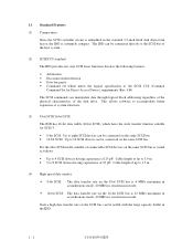
The interface between the IDD and host system is based on SCSI (Small Computer System Interface) standard [ANSI X3.131 - 1986: Small Computer System Interface (SCSI), ANSI X3.131-1994: Small Computer System Interface - 2 (SCSI-2)]. C141-E035-01EN 1 - 1 CHAPTER 1 GENERAL DESCRIPTION 1.1 Standard Features ...construct a high-performance reliable disk subsystem with an embedded SCSI controller. IDDs are high performance large capacity 3.5-inch fixed disk drives with large storage capacity. The flexibility and expandability of the SCSI, as well as the powerful command set of the intelligent...
The interface between the IDD and host system is based on SCSI (Small Computer System Interface) standard [ANSI X3.131 - 1986: Small Computer System Interface (SCSI), ANSI X3.131-1994: Small Computer System Interface - 2 (SCSI-2)]. C141-E035-01EN 1 - 1 CHAPTER 1 GENERAL DESCRIPTION 1.1 Standard Features ...construct a high-performance reliable disk subsystem with an embedded SCSI controller. IDDs are high performance large capacity 3.5-inch fixed disk drives with large storage capacity. The flexibility and expandability of the SCSI, as well as the powerful command set of the intelligent...
Product Manual
Page 17
... future expansion of system functions. (3) 8-bit SCSI/16-bit SCSI The IDD has 16-bit data width (16-bit SCSI), which meets the logical specification of the SCSI CCS (Common Command Set for SCSI-3. • 8-bit SCSI: Up to eight SCSI devices can manipulate data through logical block addressing ...IDD. 1 - 2 C141-E035-02EN The IDD can be connected directly to the SCSI bus of the disk drive. 1.1 Standard Features (1) Compactness Since the SCSI controller circuit is embedded in the standard 3.5-inch fixed disk drive form factor, the IDD is 12 MB/s maximum in asynchronous mode, 40 MB/s...
... future expansion of system functions. (3) 8-bit SCSI/16-bit SCSI The IDD has 16-bit data width (16-bit SCSI), which meets the logical specification of the SCSI CCS (Common Command Set for SCSI-3. • 8-bit SCSI: Up to eight SCSI devices can manipulate data through logical block addressing ...IDD. 1 - 2 C141-E035-02EN The IDD can be connected directly to the SCSI bus of the disk drive. 1.1 Standard Features (1) Compactness Since the SCSI controller circuit is embedded in the standard 3.5-inch fixed disk drive form factor, the IDD is 12 MB/s maximum in asynchronous mode, 40 MB/s...
Product Manual
Page 18
... feature The IDD can perform the effective input/output operations with utilizing high data transfer capability of the SCSI bus regardless of actual data transfer rate of the disk drive. (7) Read-ahead cache feature After executing the READ command, the IDD reads automatically and stores (prefetches...Note: The maximum data transfer rate in asynchronous mode may be limited by the cable length, transmission characteristics of the SCSI bus and the connected SCSI device number. (5) Continuous block processing The addressing method of data blocks is logical block address. The maximum data transfer...
... feature The IDD can perform the effective input/output operations with utilizing high data transfer capability of the SCSI bus regardless of actual data transfer rate of the disk drive. (7) Read-ahead cache feature After executing the READ command, the IDD reads automatically and stores (prefetches...Note: The maximum data transfer rate in asynchronous mode may be limited by the cable length, transmission characteristics of the SCSI bus and the connected SCSI device number. (5) Continuous block processing The addressing method of data blocks is logical block address. The maximum data transfer...

Product Manual
Page 19
...can at formatting. This results in the data buffer. (10) Error recovery The IDD can try to recover from errors in SCSI bus or the disk drive using its alternate data block. (12) Programmable data block length Data can be accessed in fixed-block length units. The initiator ...during read, the IDD can start and stop the spindle motor. (17) Diagnosis The IDD has a diagnostic capability which checks internal controller functions and drive operations to defective data block. (14) High speed positioning A rotary voice coil motor achieves fast positioning. (15) Large capacity A large capacity ...
...can at formatting. This results in the data buffer. (10) Error recovery The IDD can try to recover from errors in SCSI bus or the disk drive using its alternate data block. (12) Programmable data block length Data can be accessed in fixed-block length units. The initiator ...during read, the IDD can start and stop the spindle motor. (17) Diagnosis The IDD has a diagnostic capability which checks internal controller functions and drive operations to defective data block. (14) High speed positioning A rotary voice coil motor achieves fast positioning. (15) Large capacity A large capacity ...

Product Manual
Page 24
... 4 maximum likelihood (PR4ML) modulator and demodulator circuit to keep out dust and other pollutants. Using the movement of servo information in the vicinity of the SCSI controller. The head assembly at the end of the actuator arm is controlled and positioned via feedback of the rotating disks, air is attached.
... 4 maximum likelihood (PR4ML) modulator and demodulator circuit to keep out dust and other pollutants. Using the movement of servo information in the vicinity of the SCSI controller. The head assembly at the end of the actuator arm is controlled and positioned via feedback of the rotating disks, air is attached.

Product Manual
Page 25
...reconnect function, concurrent input/output processing is possible on which operate as initiator or connected through the SCSI bus. The IDDs perform input/output operation as specified by SCSI devices which multiple host computers that operate as initiator. 1.3 System Configuration Figure 1.8 shows the ...system configuration. For example, the system can be connected to the SCSI bus for the 8-bit SCSI and up to 16 SCSI devices operating as target. Figure 1.8 System configuration (1) SCSI bus configuration Up to the SCSI bus of host systems and are always operated as an initiator or...
...reconnect function, concurrent input/output processing is possible on which operate as initiator or connected through the SCSI bus. The IDDs perform input/output operation as specified by SCSI devices which multiple host computers that operate as initiator. 1.3 System Configuration Figure 1.8 shows the ...system configuration. For example, the system can be connected to the SCSI bus for the 8-bit SCSI and up to 16 SCSI devices operating as target. Figure 1.8 System configuration (1) SCSI bus configuration Up to the SCSI bus of host systems and are always operated as an initiator or...

Product Manual
Page 26
...disk drive is constructed so that SCSI ID, then specifies the LUN to select the peripheral device for each logical unit. (2) Addressing of peripheral device Each SCSI device on the bus has its own unique address (SCSI ID:#n in unit called as follows: • SCSI ID: 8-bit SCSI:Selectable ...from 0 to 7 (switch selectable) 16-bit SCSI:Selectable from 0 to 15 (switch selectable) • LUN:...
...disk drive is constructed so that SCSI ID, then specifies the LUN to select the peripheral device for each logical unit. (2) Addressing of peripheral device Each SCSI device on the bus has its own unique address (SCSI ID:#n in unit called as follows: • SCSI ID: 8-bit SCSI:Selectable ...from 0 to 7 (switch selectable) 16-bit SCSI:Selectable from 0 to 15 (switch selectable) • LUN:...

Product Manual
Page 28
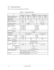
C141-E035-03EN 2 - 1 CHAPTER 2 SPECIFICATIONS 2.1 Hardware Specifications 2.2 SCSI Function Specifications This chapter describes specifications of the IDD and the functional specifications of the SCSI. 2.1 Hardware Specifications 2.1.1 Model name and part number Each model has a different data format and front panel type when shipped. (See Appendix D for the model name (type) and product number.) The data format can be changed by reinitializing with the user's system.
C141-E035-03EN 2 - 1 CHAPTER 2 SPECIFICATIONS 2.1 Hardware Specifications 2.2 SCSI Function Specifications This chapter describes specifications of the IDD and the functional specifications of the SCSI. 2.1 Hardware Specifications 2.1.1 Model name and part number Each model has a different data format and front panel type when shipped. (See Appendix D for the model name (type) and product number.) The data format can be changed by reinitializing with the user's system.
Product Manual
Page 29
...528 byte (Fixed length) ANSI X3.13-1986 and CCS (Rev. 4B) conformity (SCSI-2 ANSI X3T9.2/86-109 Rev 10h) command support SCSI-3 command partial support 512 KB FIFO ring buffer, multi-segment buffer: Segment count 1 to...-SCSI consumption (*5) Single-ended type Interface Fast SCSI Fast 20 SCSI Data transfer Disk drive rate (*8) SCSI Asynchronous mode Synchronous mode Logical data block length (*1) SCSI command specification Data buffer Specification MAA3182xx MAB3091xx MAB3045xx MAC3091xx MAC3045xx 18.2 GB 9.1 GB 4.55 GB 9.1 GB 4.55 GB 23.9 GB 11.9 GB 5.95 GB 11.8 GB 5.90 GB...
...528 byte (Fixed length) ANSI X3.13-1986 and CCS (Rev. 4B) conformity (SCSI-2 ANSI X3T9.2/86-109 Rev 10h) command support SCSI-3 command partial support 512 KB FIFO ring buffer, multi-segment buffer: Segment count 1 to...-SCSI consumption (*5) Single-ended type Interface Fast SCSI Fast 20 SCSI Data transfer Disk drive rate (*8) SCSI Asynchronous mode Synchronous mode Logical data block length (*1) SCSI command specification Data buffer Specification MAA3182xx MAB3091xx MAB3045xx MAC3091xx MAC3045xx 18.2 GB 9.1 GB 4.55 GB 9.1 GB 4.55 GB 23.9 GB 11.9 GB 5.95 GB 11.8 GB 5.90 GB...
Product Manual
Page 30
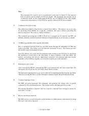
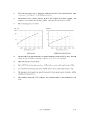
... and using spare sector space. The number of user cylinders and alternate cylinders can use cable length of up to 3.0 m. (*7) 5 to 8 SCSI devices having capacitance of 25pF or less can be specified at format of user cylinders indicates the max., and includes the alternate cylinder. C141-E035... 2 - 3 See Chapter 3 for disks to completely stop from power off or stop command. (*5) This value indicates at ready mode. (*6) Up to 4 SCSI devices having capacitance of 25pF or less can use cable length of up to other terminators is the time for the further information. (*2) The number...
... and using spare sector space. The number of user cylinders and alternate cylinders can use cable length of up to 3.0 m. (*7) 5 to 8 SCSI devices having capacitance of 25pF or less can be specified at format of user cylinders indicates the max., and includes the alternate cylinder. C141-E035... 2 - 3 See Chapter 3 for disks to completely stop from power off or stop command. (*5) This value indicates at ready mode. (*6) Up to 4 SCSI devices having capacitance of 25pF or less can use cable length of up to other terminators is the time for the further information. (*2) The number...

