Product Manual
Page 6
... SCSI controller. Chapter 1 GENERAL DESCRIPTION This chapter introduces the MAA31xxxx, MAB30xxxx and MAC30xxxx series disk drives and discusses their installation environment. This manual details the specifications and functions of model names and product numbers, and SCSI interface functions. It includes the notice and procedures for installing MAA31xxxx, MAB30xxxx and MAC30xxxx series disk drives. C141-E035-03EN v Chapter 5 INSTALLATION This chapter explains how to do about media defects. Chapter 3 DATA FORMAT...
... SCSI controller. Chapter 1 GENERAL DESCRIPTION This chapter introduces the MAA31xxxx, MAB30xxxx and MAC30xxxx series disk drives and discusses their installation environment. This manual details the specifications and functions of model names and product numbers, and SCSI interface functions. It includes the notice and procedures for installing MAA31xxxx, MAB30xxxx and MAC30xxxx series disk drives. C141-E035-03EN v Chapter 5 INSTALLATION This chapter explains how to do about media defects. Chapter 3 DATA FORMAT...
Product Manual
Page 8
... conditions, power trouble, host problems, cable failures, or any failure not caused by the drive itself. The suffix of the model name of the disk drive varies depending on the electrical requirements, capacity, and data format at factory shipment of the MAA31xxxx, MAB30xxxx and MAC30xxxx series intelligent disk drive is not responsible for connecting the three device types or host system and the disk drives (Note 1). Fujitsu is defined as a failure requiring adjustments, repairs, or replacement.
... conditions, power trouble, host problems, cable failures, or any failure not caused by the drive itself. The suffix of the model name of the disk drive varies depending on the electrical requirements, capacity, and data format at factory shipment of the MAA31xxxx, MAB30xxxx and MAC30xxxx series intelligent disk drive is not responsible for connecting the three device types or host system and the disk drives (Note 1). Fujitsu is defined as a failure requiring adjustments, repairs, or replacement.
Product Manual
Page 9
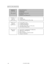
MANUAL ORGANIZATION PRODUCT MANUAL (This manual) SCSI Physical Interface Specifications SCSI Logical Interface Specifications Maintenance Manual 1. Installation Requirements 5. Installation 6. Sense Data and error Recovery Procedure 5. SCSI Bus Error Recovery Processing 1. Command Processing 2. SCSI Message 3. Specifications and Equipment Configuration 2. Principle of Operation viii C141-E035-03EN SCSI Bus 2. Disk Medium Management 1. Data Format 4. Command Specification 4. Error Analysis 4. Maintenance and Diagnostic 3. Specifications 3. General Description ...
MANUAL ORGANIZATION PRODUCT MANUAL (This manual) SCSI Physical Interface Specifications SCSI Logical Interface Specifications Maintenance Manual 1. Installation Requirements 5. Installation 6. Sense Data and error Recovery Procedure 5. SCSI Bus Error Recovery Processing 1. Command Processing 2. SCSI Message 3. Specifications and Equipment Configuration 2. Principle of Operation viii C141-E035-03EN SCSI Bus 2. Disk Medium Management 1. Data Format 4. Command Specification 4. Error Analysis 4. Maintenance and Diagnostic 3. Specifications 3. General Description ...
Product Manual
Page 11
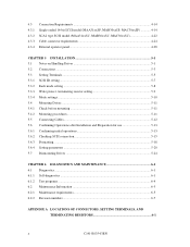
...4-14 SCA2 type SCSI model (MAA31xxSC, MAB30xxSC, MAC30xxSC 4-22 Cable connector requirements 4-24 External operator panel 4-28 CHAPTER 5 INSTALLATION 5-1 5.1 Notes on Handling Drives 5-1 5.2 Connections...5-3 5.3 Setting Terminals...5-5 5.3.1 SCSI ID setting...5-7 5.3.2 Each mode setting ...5-8 5.3.3 Write protect, terminating resistor setting 5-9 5.3.4 Mode settings ...5-10 5.4 Mounting Drives ...5-11 5.4.1 Check before mounting 5-11 5.4.2 Mounting procedures...5-11 5.5 Connecting Cables...5-12 5.6 Confirming Operations after Installation and Preparation for use 5-13 5.6.1 Confirming...
...4-14 SCA2 type SCSI model (MAA31xxSC, MAB30xxSC, MAC30xxSC 4-22 Cable connector requirements 4-24 External operator panel 4-28 CHAPTER 5 INSTALLATION 5-1 5.1 Notes on Handling Drives 5-1 5.2 Connections...5-3 5.3 Setting Terminals...5-5 5.3.1 SCSI ID setting...5-7 5.3.2 Each mode setting ...5-8 5.3.3 Write protect, terminating resistor setting 5-9 5.3.4 Mode settings ...5-10 5.4 Mounting Drives ...5-11 5.4.1 Check before mounting 5-11 5.4.2 Mounting procedures...5-11 5.5 Connecting Cables...5-12 5.6 Confirming Operations after Installation and Preparation for use 5-13 5.6.1 Confirming...
Product Manual
Page 15
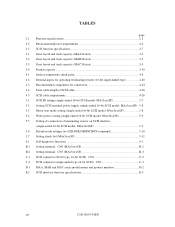
...bit SCSI model: MAx3xxxSP 5-9 5.5 Setting of connection of terminating resistor on SCSI interface (single-ended 16-bit SCSI model: MAx3xxxSP 5-9 5.6 Default mode settings (by CHANGE DEFINITION command 5-10 5.7 Setting check list (MAx3xxxSP 5-11 6.1 Self-diagnostic functions 6-1 B.1 Setting terminal: CN6 (MAx3xxxSP B-2 B.2 Setting terminal: CN7 (MAx3xxxSP B-3 C.1 SCSI connector (SCA2 type, 16-bit SCSI): CN1 C-2 C.2 SCSI connector (single-ended type 16-bit SCSI): CN1 C-3 D.1 MAA, MAB and MAC series model names and product numbers D-2 E.1 SCSI interface function specifications E-2 xiv...
...bit SCSI model: MAx3xxxSP 5-9 5.5 Setting of connection of terminating resistor on SCSI interface (single-ended 16-bit SCSI model: MAx3xxxSP 5-9 5.6 Default mode settings (by CHANGE DEFINITION command 5-10 5.7 Setting check list (MAx3xxxSP 5-11 6.1 Self-diagnostic functions 6-1 B.1 Setting terminal: CN6 (MAx3xxxSP B-2 B.2 Setting terminal: CN7 (MAx3xxxSP B-3 C.1 SCSI connector (SCA2 type, 16-bit SCSI): CN1 C-2 C.2 SCSI connector (single-ended type 16-bit SCSI): CN1 C-3 D.1 MAA, MAB and MAC series model names and product numbers D-2 E.1 SCSI interface function specifications E-2 xiv...
Product Manual
Page 17
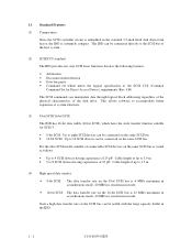
... Access Device) requirements (Rev. 4.B) The SCSI commands can be connected on the same SCSI bus. • 16-bit SCSI: Up to 1.5 m (4) High speed data transfer • 8-bit SCSI: The data transfer rate on the 8-bit SCSI bus is 6 MB/s maximum in asynchronous mode, 20 MB/s in synchronous mode. • 16-bit SCSI: The data transfer rate on the same SCSI bus. This allows software to accommodate future expansion of the SCSI CCS (Common Command Set for SCSI...
... Access Device) requirements (Rev. 4.B) The SCSI commands can be connected on the same SCSI bus. • 16-bit SCSI: Up to 1.5 m (4) High speed data transfer • 8-bit SCSI: The data transfer rate on the 8-bit SCSI bus is 6 MB/s maximum in asynchronous mode, 20 MB/s in synchronous mode. • 16-bit SCSI: The data transfer rate on the same SCSI bus. This allows software to accommodate future expansion of the SCSI CCS (Common Command Set for SCSI...
Product Manual
Page 18
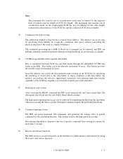
... the disk drive. (7) Read-ahead cache feature After executing the READ command, the IDD reads automatically and stores (prefetches) the subsequent data blocks into maximum 16 areas. This buffer can perform continuous read/write operation when processing data blocks on several tracks or cylinder. (6) 512 KB programmable multi-segment data buffer Data is logical block address. Since the initiator can control the disconnect/reconnect timing on the SCSI bus...
... the disk drive. (7) Read-ahead cache feature After executing the READ command, the IDD reads automatically and stores (prefetches) the subsequent data blocks into maximum 16 areas. This buffer can perform continuous read/write operation when processing data blocks on several tracks or cylinder. (6) 512 KB programmable multi-segment data buffer Data is logical block address. Since the initiator can control the disconnect/reconnect timing on the SCSI bus...
Product Manual
Page 29
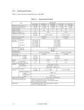
... Formatted capacity/device (*1) Unformatted capacity/device Number of disks Number of heads Number of cylinders (*2) Unformatted capacity/track Number of the IDD. 2.1.2 Function specifications Table 2.1 shows the function specifications of rotations (rpm) Average latency time Seek time (*3) Minimum (Read/Write) Average Maximum Start/stop time Start time (*4) Stop time Recording mode Recording density Track density External dimensions Height Width Depth Weight Power 16bit-SCSI consumption (*5) Single-ended type Interface Fast SCSI Fast 20 SCSI Data transfer Disk drive rate...
... Formatted capacity/device (*1) Unformatted capacity/device Number of disks Number of heads Number of cylinders (*2) Unformatted capacity/track Number of the IDD. 2.1.2 Function specifications Table 2.1 shows the function specifications of rotations (rpm) Average latency time Seek time (*3) Minimum (Read/Write) Average Maximum Start/stop time Start time (*4) Stop time Recording mode Recording density Track density External dimensions Height Width Depth Weight Power 16bit-SCSI consumption (*5) Single-ended type Interface Fast SCSI Fast 20 SCSI Data transfer Disk drive rate...
Product Manual
Page 30
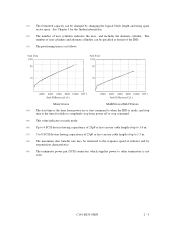
... terminator power pin (SCSI connector) which supplies power to other terminators is not used. (*1) The formatted capacity can use cable length of up to 3.0 m. (*7) 5 to 8 SCSI devices having capacitance of 25pF or less can use cable length of up to 1.5 m. (*8) The maximum data transfer rate may be restricted to the response speed of initiator and by changing the logical block length and using spare sector space. The number of user cylinders and alternate cylinders can be...
... terminator power pin (SCSI connector) which supplies power to other terminators is not used. (*1) The formatted capacity can use cable length of up to 3.0 m. (*7) 5 to 8 SCSI devices having capacitance of 25pF or less can use cable length of up to 1.5 m. (*8) The maximum data transfer rate may be restricted to the response speed of initiator and by changing the logical block length and using spare sector space. The number of user cylinders and alternate cylinders can be...
Product Manual
Page 32
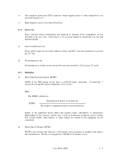
... initialization and replaced by alternate block assignments are not considered. (2) Mean Time To Repair (MTTR) MTTR is the average time taken by a well-trained service mechanic to bad environmental conditions, power trouble, host system trouble, cable failures, or other terminators is not used (See Section 4.3). (*7) High frequency noise is less than 100 mVp-p. 2.1.4 Error rate Errors detected during its life time is defined as: MTBF= Operating time (hours...
... initialization and replaced by alternate block assignments are not considered. (2) Mean Time To Repair (MTTR) MTTR is the average time taken by a well-trained service mechanic to bad environmental conditions, power trouble, host system trouble, cable failures, or other terminators is not used (See Section 4.3). (*7) High frequency noise is less than 100 mVp-p. 2.1.4 Error rate Errors detected during its life time is defined as: MTBF= Operating time (hours...
Product Manual
Page 39
... (P list and G list) • MODE SELECT parameter (saved value) • Statistical information (log data) • Controller control information The above information are recorded. The IDD reads or writes the data block in the Internal test space during the self-diagnostic test specified with the MODE SELECT or MODE SELECT EXTENDED command. The data format on the user space (the length of data block and the number of data blocks) can also specify the number of the IDD itself...
... (P list and G list) • MODE SELECT parameter (saved value) • Statistical information (log data) • Controller control information The above information are recorded. The IDD reads or writes the data block in the Internal test space during the self-diagnostic test specified with the MODE SELECT or MODE SELECT EXTENDED command. The data format on the user space (the length of data block and the number of data blocks) can also specify the number of the IDD itself...
Product Manual
Page 80
...Notes on Handling Drives 5.2 Connections 5.3 Setting Terminals 5.4 Mounting Drives 5.5 Connecting Cables 5.6 Confirming Operations after Installation and Preparation for Use 5.7 Dismounting Drives This chapter describes the notes on handling drives, connections, setting switches and plugs, mounting drives, connecting cables, confirming drive operations after installation and preparation for setting. (2) Unpackaging a) Use a flat work area. Especially be careful when unpacking. c) Be careful not to give excess pressure to the PCAs and interface connector when removing the drive from the...
...Notes on Handling Drives 5.2 Connections 5.3 Setting Terminals 5.4 Mounting Drives 5.5 Connecting Cables 5.6 Confirming Operations after Installation and Preparation for Use 5.7 Dismounting Drives This chapter describes the notes on handling drives, connections, setting switches and plugs, mounting drives, connecting cables, confirming drive operations after installation and preparation for setting. (2) Unpackaging a) Use a flat work area. Especially be careful when unpacking. c) Be careful not to give excess pressure to the PCAs and interface connector when removing the drive from the...
Product Manual
Page 97
... code = 3) and drive parameter (page code = 4). 5 - 18 C141-E035-02EN Otherwise, specify 0 in the user space • Alternate spare area size This section outlines the formatting at abnormal end a) When sense data can be obtained with the REQUEST SENSE command, analyze the sense data and retry recovery for each model (part number) when shipped from the default format, all sides of SCSI Logical Interface Specifications for the SCSI cable connection: • All connectors...
... code = 3) and drive parameter (page code = 4). 5 - 18 C141-E035-02EN Otherwise, specify 0 in the user space • Alternate spare area size This section outlines the formatting at abnormal end a) When sense data can be obtained with the REQUEST SENSE command, analyze the sense data and retry recovery for each model (part number) when shipped from the default format, all sides of SCSI Logical Interface Specifications for the SCSI cable connection: • All connectors...
Product Manual
Page 99
... reset. To obtain the best performance, set by the user when power is turned on again. This enables the IDD to the saved parameter value if the saving operation is not executed at installation. 5 - 20 C141-E035-02EN In the multi-INIT System, parameter setting cannot be set or saved with the MODE SELECT or MODE SELECT EXTENDED command: • Error recovery parameter • Disconnection/reconnection parameter • Caching parameter • Control mode parameter With the MODE SELECT...
... reset. To obtain the best performance, set by the user when power is turned on again. This enables the IDD to the saved parameter value if the saving operation is not executed at installation. 5 - 20 C141-E035-02EN In the multi-INIT System, parameter setting cannot be set or saved with the MODE SELECT or MODE SELECT EXTENDED command: • Error recovery parameter • Disconnection/reconnection parameter • Caching parameter • Control mode parameter With the MODE SELECT...
Product Manual
Page 101
... Interface Specifications for the parameter values to transfer data on the SCSI bus at a read (READ or READ EXTENDED command) or write operation (WRITE, WRITE EXTENDED, or WRITE AND VERIFY command) of reconnection processing to be specified. 2. a. Disconnection/reconnection parameters (page code = 2) • Buffer full ratio • Buffer empty ratio Parameter Default value 20 (HEX) 20 (HEX) Notes: 1. Notes: 1. In a system without the disconnection function, these parameters need not be set. Determine the parameter...
... Interface Specifications for the parameter values to transfer data on the SCSI bus at a read (READ or READ EXTENDED command) or write operation (WRITE, WRITE EXTENDED, or WRITE AND VERIFY command) of reconnection processing to be specified. 2. a. Disconnection/reconnection parameters (page code = 2) • Buffer full ratio • Buffer empty ratio Parameter Default value 20 (HEX) 20 (HEX) Notes: 1. Notes: 1. In a system without the disconnection function, these parameters need not be set. Determine the parameter...
Product Manual
Page 103
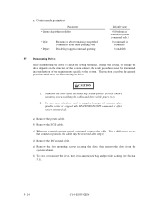
... cables and drive while power is stopped with START/STOP UNIT command or after disconnecting system power. e) Remove the four mounting screws securing the drive, then remove the drive from the system cabinet. a. Control mode parameters Parameter • Queue algorithm modifier • QErr: • DQue: Resume or abort remaining suspended commands after sense pending state Disabling tagged command queuing Default value 0 (Ordering is executed by read command only.) 0 (command is mounted, remove...
... cables and drive while power is stopped with START/STOP UNIT command or after disconnecting system power. e) Remove the four mounting screws securing the drive, then remove the drive from the system cabinet. a. Control mode parameters Parameter • Queue algorithm modifier • QErr: • DQue: Resume or abort remaining suspended commands after sense pending state Disabling tagged command queuing Default value 0 (Ordering is executed by read command only.) 0 (command is mounted, remove...
Product Manual
Page 109
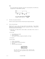
... repairs Fujitsu has the service system and repair facility for replacing or repairing the disk drive. Fujitsu does not assume responsibility if data is operating. (3) Parts that can be replaced in the field The PCA cannot be included: a) IDD model, part number (P/N), revision number, serial number (S/N), and date of manufacturing b) Error status • Date when the error occurred • System configuration • Environmental conditions (temperature, humidity, and voltage) c) Error history d) Error contents • Outline of inconvenience • Issued commands...
... repairs Fujitsu has the service system and repair facility for replacing or repairing the disk drive. Fujitsu does not assume responsibility if data is operating. (3) Parts that can be replaced in the field The PCA cannot be included: a) IDD model, part number (P/N), revision number, serial number (S/N), and date of manufacturing b) Error status • Date when the error occurred • System configuration • Environmental conditions (temperature, humidity, and voltage) c) Error history d) Error contents • Outline of inconvenience • Issued commands...
Product Manual
Page 136
...1-2 Confirming Operations after Installation for use 5-13 Confirming initial operations 5-13 Connection of terminating resistor 5-9 Connection requirements 4-14 Connections 5-3 Connector signal Allocation C-2 Connector signal allocation C-1 Connectors of terminals location 4-14, 4-22 Contact start/stop 1-8 Continuous block processing 1-3 Control mode parameters 5-23 Controller circuit 1-9 Current waveform 4-11 Cylinder configuration 3-1, 3-2 Cylinder skew 3-7 D D list 3-12 DC ground 4-27 DE 1-9 DISCON 4-20 Data field 3-8 Data format 3-1 Data security at power-failure 2-6 Data space 3-1 Default...
...1-2 Confirming Operations after Installation for use 5-13 Confirming initial operations 5-13 Connection of terminating resistor 5-9 Connection requirements 4-14 Connections 5-3 Connector signal Allocation C-2 Connector signal allocation C-1 Connectors of terminals location 4-14, 4-22 Contact start/stop 1-8 Continuous block processing 1-3 Control mode parameters 5-23 Controller circuit 1-9 Current waveform 4-11 Cylinder configuration 3-1, 3-2 Cylinder skew 3-7 D D list 3-12 DC ground 4-27 DE 1-9 DISCON 4-20 Data field 3-8 Data format 3-1 Data security at power-failure 2-6 Data space 3-1 Default...
Product Manual
Page 137
... External operator panel connector signals 4-18 F FG 4-27 FORMAT UNIT command 5-19 Format capacity 3-10 Format parameter 5-19 Formatting 2-6 Function specifications 2-2 G G list 3-12 G1 3-8 Gaps 3-8 General description 1-1 General notes 5-1 General notes 5-1 H Hardware function test 6-2 Head configuration 1-8 Heads 1-8 High speed data transfer 1-2 High speed positioning 1-4 Humidity 2-4 I Indicating revision number 6-7 Initial self-diagnostics 6-2 Input signal 4-19, 4-20 Installation 5-1, 5-2 Installation requirements 4-1 Inteface connector 4-15 Interface test 6-5 Internal test space 3-4 L LBA...
... External operator panel connector signals 4-18 F FG 4-27 FORMAT UNIT command 5-19 Format capacity 3-10 Format parameter 5-19 Formatting 2-6 Function specifications 2-2 G G list 3-12 G1 3-8 Gaps 3-8 General description 1-1 General notes 5-1 General notes 5-1 H Hardware function test 6-2 Head configuration 1-8 Heads 1-8 High speed data transfer 1-2 High speed positioning 1-4 Humidity 2-4 I Indicating revision number 6-7 Initial self-diagnostics 6-2 Input signal 4-19, 4-20 Installation 5-1, 5-2 Installation requirements 4-1 Inteface connector 4-15 Interface test 6-5 Internal test space 3-4 L LBA...
Product Manual
Page 138
...segment data buffer 1-3 R Random read test 6-5 Read circuit 1-9 Read-ahead cache feature 1-3 Read/write error recovery parameter 5-21 Recirculation filter 1-9 Recommended components for connection 4- 21, 4-24 Reconnection parameter 5-22 Release function 1-3 Reliability 2-5 Reporting result of self-diagnostics 6-3 Reserve function 1-3 Revision label 6-7 Revision numbers 6-7 S SA space 3-4 SB 3-8 SCA2 type SCSI model 4-22 SCSI ID 1-11 SCSI ID external input 4-18 SCSI bus configuration 1-10 SCSI bus connection 5-3 SCSI bus test 6-5 SCSI cable 4-25 SCSI cable connector 4-25 SCSI cable requirements...
...segment data buffer 1-3 R Random read test 6-5 Read circuit 1-9 Read-ahead cache feature 1-3 Read/write error recovery parameter 5-21 Recirculation filter 1-9 Recommended components for connection 4- 21, 4-24 Reconnection parameter 5-22 Release function 1-3 Reliability 2-5 Reporting result of self-diagnostics 6-3 Reserve function 1-3 Revision label 6-7 Revision numbers 6-7 S SA space 3-4 SB 3-8 SCA2 type SCSI model 4-22 SCSI ID 1-11 SCSI ID external input 4-18 SCSI bus configuration 1-10 SCSI bus connection 5-3 SCSI bus test 6-5 SCSI cable 4-25 SCSI cable connector 4-25 SCSI cable requirements...


