Product Manual
Page 6
..., and what to install MAA31xxxx, MAB30xxxx and MAC30xxxx series disk drives. Chapter 5 INSTALLATION This chapter explains how to do about media defects. This manual details the specifications and functions of model names and product numbers, and SCSI interface functions. Chapter 2 ...procedures for installing MAA31xxxx, MAB30xxxx and MAC30xxxx series disk drives. C141-E035-03EN v This manual is written for installing it into a host computer system. The model numbers have a basic understanding of fixed disk drives and their use the other manuals. The need arises,...
..., and what to install MAA31xxxx, MAB30xxxx and MAC30xxxx series disk drives. Chapter 5 INSTALLATION This chapter explains how to do about media defects. This manual details the specifications and functions of model names and product numbers, and SCSI interface functions. Chapter 2 ...procedures for installing MAA31xxxx, MAB30xxxx and MAC30xxxx series disk drives. C141-E035-03EN v This manual is written for installing it into a host computer system. The model numbers have a basic understanding of fixed disk drives and their use the other manuals. The need arises,...
Product Manual
Page 8
Fujitsu is defined as a failure requiring adjustments, repairs, or replacement. Note 1: Model names M AA 3 182 SC Interface types SP: Single-Ended, 16-bit SCSI SC: Single-Ended, 16-bit SCSI SCA2 connector Formatted ... MAA3182 MAB3091 MAB3045 MAC3091 MAC3045 Model name MAA3182SP, MAA3182SC MAB3091SP, MAB3091SC MAB3045SP, MAB3045SC MAC3091SP, MAC3091SC MAC3045SP, MAC3045SC C141-E035-03EN vii DISCLAIMER Failure of the SCSI, i.e., the interface for drive failures caused by misuse by the user, poor environmental conditions, power trouble, host problems, cable failures, or any ...
Fujitsu is defined as a failure requiring adjustments, repairs, or replacement. Note 1: Model names M AA 3 182 SC Interface types SP: Single-Ended, 16-bit SCSI SC: Single-Ended, 16-bit SCSI SCA2 connector Formatted ... MAA3182 MAB3091 MAB3045 MAC3091 MAC3045 Model name MAA3182SP, MAA3182SC MAB3091SP, MAB3091SC MAB3045SP, MAB3045SC MAC3091SP, MAC3091SC MAC3045SP, MAC3045SC C141-E035-03EN vii DISCLAIMER Failure of the SCSI, i.e., the interface for drive failures caused by misuse by the user, poor environmental conditions, power trouble, host problems, cable failures, or any ...

Product Manual
Page 10
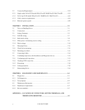
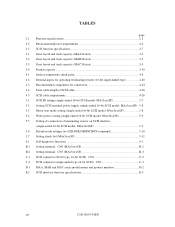
CONTENTS page CHAPTER 1 GENERAL DESCRIPTION 1-1 1.1 Standard Features ...1-2 1.2 Hardware Structure...1-5 1.3 System Configuration...1-10 CHAPTER 2 SPECIFICATIONS 2-1 2.1 Hardware Specifications 2-1 2.1.1 Model name and part number 2-1 2.1.2 Function specifications 2-2 2.1.3 Environmental specifications 2-4 2.1.4 Error rate...2-5 2.1.5 Reliability ...2-5 2.2 SCSI Function Specifications 2-7 CHAPTER 3 DATA FORMAT 3-1 3.1 Data Space...3-1 3.1.1 Cylinder configuration...3-1 3.1.2 Alternate spare area ...3-5 3.1.3 Track ...
CONTENTS page CHAPTER 1 GENERAL DESCRIPTION 1-1 1.1 Standard Features ...1-2 1.2 Hardware Structure...1-5 1.3 System Configuration...1-10 CHAPTER 2 SPECIFICATIONS 2-1 2.1 Hardware Specifications 2-1 2.1.1 Model name and part number 2-1 2.1.2 Function specifications 2-2 2.1.3 Environmental specifications 2-4 2.1.4 Error rate...2-5 2.1.5 Reliability ...2-5 2.2 SCSI Function Specifications 2-7 CHAPTER 3 DATA FORMAT 3-1 3.1 Data Space...3-1 3.1.1 Cylinder configuration...3-1 3.1.2 Alternate spare area ...3-5 3.1.3 Track ...
Product Manual
Page 11
...model (MAA31xxSP, MAB30xxSP, MAC30xxSP 4-14 SCA2 type SCSI model (MAA31xxSC, MAB30xxSC, MAC30xxSC 4-22 Cable connector requirements 4-24 External operator panel 4-28 CHAPTER 5 INSTALLATION 5-1 5.1 Notes on Handling Drives 5-1 5.2 Connections...5-3 5.3 Setting Terminals...5-5 5.3.1 SCSI ID setting...5-7 5.3.2 Each mode setting ...5-8 5.3.3 Write protect, terminating resistor setting 5-9 5.3.4 Mode settings ...5-10 5.4 Mounting Drives... 5.6.3 Formatting ...5-18 5.6.4 Setting parameters ...5-20 5.7 Dismounting Drives ...5-24 CHAPTER 6 DIAGNOSTICS AND MAINTENANCE 6-1 6.1 Diagnostics ...6-1...
...model (MAA31xxSP, MAB30xxSP, MAC30xxSP 4-14 SCA2 type SCSI model (MAA31xxSC, MAB30xxSC, MAC30xxSC 4-22 Cable connector requirements 4-24 External operator panel 4-28 CHAPTER 5 INSTALLATION 5-1 5.1 Notes on Handling Drives 5-1 5.2 Connections...5-3 5.3 Setting Terminals...5-5 5.3.1 SCSI ID setting...5-7 5.3.2 Each mode setting ...5-8 5.3.3 Write protect, terminating resistor setting 5-9 5.3.4 Mode settings ...5-10 5.4 Mounting Drives... 5.6.3 Formatting ...5-18 5.6.4 Setting parameters ...5-20 5.7 Dismounting Drives ...5-24 CHAPTER 6 DIAGNOSTICS AND MAINTENANCE 6-1 6.1 Diagnostics ...6-1...

Product Manual
Page 12
... SCSI B-2 APPENDIX C CONNECTOR SIGNAL ALLOCATION C-1 C.1 SCSI Connector Signal Allocation: SCA2 type 16-bit SCSI C-2 C.2 SCSI Connector Signal Allocation: Single-ended type 16-bit SCSI C-3 APPENDIX D MODEL NAMES AND PRODUCT NUMBERS D-1 D.1 Model Names and Product Numbers D-2 APPENDIX E SCSI INTERFACE FUNCTIONS E-1 E.1 SCSI interface function specifications E-2 Index...IN-1 C141-E035-03EN xi
... SCSI B-2 APPENDIX C CONNECTOR SIGNAL ALLOCATION C-1 C.1 SCSI Connector Signal Allocation: SCA2 type 16-bit SCSI C-2 C.2 SCSI Connector Signal Allocation: Single-ended type 16-bit SCSI C-3 APPENDIX D MODEL NAMES AND PRODUCT NUMBERS D-1 D.1 Model Names and Product Numbers D-2 APPENDIX E SCSI INTERFACE FUNCTIONS E-1 E.1 SCSI interface function specifications E-2 Index...IN-1 C141-E035-03EN xi

Product Manual
Page 14
... supply connector (16-bit SCSI model 4-15 4.19 External operator panel connector (CN1 4-16 4.20 External operator panel connector (CN7 4-17 4.21 16-bit SCSI ID external input 4-18 4.22 Output signal for external LED 4-19 4.23 Cables connection (16-bit SCSI model 4-21 4.24 Connectors and terminals... location of SCA2 type SCSI model 4-22 4.25 SCA2 type SCSI connector 4-23 4.26 SCSI cable connector...4-25 4.27 SCSI cable termination 4-27 4....
... supply connector (16-bit SCSI model 4-15 4.19 External operator panel connector (CN1 4-16 4.20 External operator panel connector (CN7 4-17 4.21 16-bit SCSI ID external input 4-18 4.22 Output signal for external LED 4-19 4.23 Cables connection (16-bit SCSI model 4-21 4.24 Connectors and terminals... location of SCA2 type SCSI model 4-22 4.25 SCA2 type SCSI connector 4-23 4.26 SCSI cable connector...4-25 4.27 SCSI cable termination 4-27 4....
Product Manual
Page 15
... requirements 4-26 5.1 SCSI ID setting (single-ended 16-bit SCSI model: MAx3xxxSP 5-7 5.2 Setting SCSI terminal power supply (single-ended 16-bit SCSI model: MAx3xxxSP) . 5-8 5.3 Motor start mode setting (single-ended 16-bit SCSI model: MAx3xxxSP 5-8 5.4 Write protect setting (single-ended 16-bit SCSI model: MAx3xxxSP 5-9 5.5 Setting of connection of terminating resistor on SCSI interface...
... requirements 4-26 5.1 SCSI ID setting (single-ended 16-bit SCSI model: MAx3xxxSP 5-7 5.2 Setting SCSI terminal power supply (single-ended 16-bit SCSI model: MAx3xxxSP) . 5-8 5.3 Motor start mode setting (single-ended 16-bit SCSI model: MAx3xxxSP 5-8 5.4 Write protect setting (single-ended 16-bit SCSI model: MAx3xxxSP 5-9 5.5 Setting of connection of terminating resistor on SCSI interface...
Product Manual
Page 17
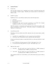
...devices having capacitance of 25 pF: Cable length of up to accommodate future expansion of the disk drive. 1.1 Standard Features (1) Compactness Since the SCSI controller circuit is embedded in the standard 3.5-inch fixed disk drive form factor, the IDD is 12 MB/s maximum in asynchronous mode, 40 MB/s in synchronous... the 8-bit SCSI bus is 6 MB/s maximum in asynchronous mode, 20 MB/s in the IDD. 1 - 2 C141-E035-02EN For the ultra SCSI model, number of connectable SCSI devices on the SCSI bus can be useful with the large capacity buffer in synchronous mode. • 16-bit SCSI: The...
...devices having capacitance of 25 pF: Cable length of up to accommodate future expansion of the disk drive. 1.1 Standard Features (1) Compactness Since the SCSI controller circuit is embedded in the standard 3.5-inch fixed disk drive form factor, the IDD is 12 MB/s maximum in asynchronous mode, 40 MB/s in synchronous... the 8-bit SCSI bus is 6 MB/s maximum in asynchronous mode, 20 MB/s in the IDD. 1 - 2 C141-E035-02EN For the ultra SCSI model, number of connectable SCSI devices on the SCSI bus can be useful with the large capacity buffer in synchronous mode. • 16-bit SCSI: The...

Product Manual
Page 23
... are in contact with the disks when the disks are not rotating, and automatically float when the rotation is controlled by a direct-drive hall-less DC motor. The disks are rotated by a feedback circuit using the counter electromotive current to precisely maintain the speed at ... Resistive) of 25 mm (0.98 inch). MAA3182:10 MAB3091, MAC3091:5 MAB3045, MAC3045:3 (2) Heads The MR (Magnet - The motor speed is started. Each model contains following number of the specified speed. 1 - 8 C141-E035-03EN Figure 1.7 Disk/head configuration (3) Spindle motor The disks are good for at ±...
... are in contact with the disks when the disks are not rotating, and automatically float when the rotation is controlled by a direct-drive hall-less DC motor. The disks are rotated by a feedback circuit using the counter electromotive current to precisely maintain the speed at ... Resistive) of 25 mm (0.98 inch). MAA3182:10 MAB3091, MAC3091:5 MAB3045, MAC3045:3 (2) Heads The MR (Magnet - The motor speed is started. Each model contains following number of the specified speed. 1 - 8 C141-E035-03EN Figure 1.7 Disk/head configuration (3) Spindle motor The disks are good for at ±...

Product Manual
Page 28
C141-E035-03EN 2 - 1 CHAPTER 2 SPECIFICATIONS 2.1 Hardware Specifications 2.2 SCSI Function Specifications This chapter describes specifications of the IDD and the functional specifications of the SCSI. 2.1 Hardware Specifications 2.1.1 Model name and part number Each model has a different data format and front panel type when shipped. (See Appendix D for the model name (type) and product number.) The data format can be changed by reinitializing with the user's system.
C141-E035-03EN 2 - 1 CHAPTER 2 SPECIFICATIONS 2.1 Hardware Specifications 2.2 SCSI Function Specifications This chapter describes specifications of the IDD and the functional specifications of the SCSI. 2.1 Hardware Specifications 2.1.1 Model name and part number Each model has a different data format and front panel type when shipped. (See Appendix D for the model name (type) and product number.) The data format can be changed by reinitializing with the user's system.
Product Manual
Page 45
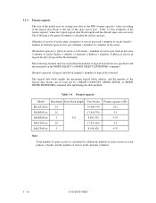
...the zone] [Formatted capacity] = [total of sectors of all zones] - [number of sectors per track × number of tracks (heads) - Table 3.4 Format capacity Model Data heads Data block length MAA3182xx 19 MAB3091xx 10 MAB3045xx 5 512 MAC3091xx 10 MAC3045xx 5 User blocks 35,680,750 17,824,700 8,895,370 17...,871,600 8,918,420 Format capacity (GB) 18.2 9.1 4.55 9.1 4.55 Note: Total number of spare sectors is the general formula to the logical data block or the size of the ...
...the zone] [Formatted capacity] = [total of sectors of all zones] - [number of sectors per track × number of tracks (heads) - Table 3.4 Format capacity Model Data heads Data block length MAA3182xx 19 MAB3091xx 10 MAB3045xx 5 512 MAC3091xx 10 MAC3045xx 5 User blocks 35,680,750 17,824,700 8,895,370 17...,871,600 8,918,420 Format capacity (GB) 18.2 9.1 4.55 9.1 4.55 Note: Total number of spare sectors is the general formula to the logical data block or the size of the ...

Product Manual
Page 65
4.3 Connection Requirements 4.3.1 Single-ended 16-bit SCSI model (MAA31xxSP, MAB30xxSP, MAC30xxSP) (1) Connectors Figures 4.16 show the locations of connectors and terminals on the single-ended 16-bit SCSI model. • Power supply connector • SCSI connector • External operator panel connector External operator panel Spindle sync connector (CN7) Power supply connector (CN1) External operator panel connector (CN1) SCSI connector (CN1) Figure 4.16 Connectors and terminals location (single-ended 16-bit SCSI) 4 - 14 C141-E035-03EN
4.3 Connection Requirements 4.3.1 Single-ended 16-bit SCSI model (MAA31xxSP, MAB30xxSP, MAC30xxSP) (1) Connectors Figures 4.16 show the locations of connectors and terminals on the single-ended 16-bit SCSI model. • Power supply connector • SCSI connector • External operator panel connector External operator panel Spindle sync connector (CN7) Power supply connector (CN1) External operator panel connector (CN1) SCSI connector (CN1) Figure 4.16 Connectors and terminals location (single-ended 16-bit SCSI) 4 - 14 C141-E035-03EN

Product Manual
Page 67
Also, a connector for DC grounding. Figure 4.18 Power supply connector (16-bit SCSI model) (3) SG terminal The IDD is not provided with an SG terminal (fasten tab) for the external operator panel are provided on the IDD as shown ...
Also, a connector for DC grounding. Figure 4.18 Power supply connector (16-bit SCSI model) (3) SG terminal The IDD is not provided with an SG terminal (fasten tab) for the external operator panel are provided on the IDD as shown ...

Product Manual
Page 72
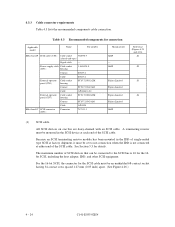
Recommended components for cable connection between the IDD, host system, and power supply unit are listed in Figure 4.23. (6) Cable connection requirements The requirements for connection are given in Table 4.1. External operator panel (example) Figure 4.23 Cables connection (16-bit SCSI model) C141-E035-02EN 4 - 21
Recommended components for cable connection between the IDD, host system, and power supply unit are listed in Figure 4.23. (6) Cable connection requirements The requirements for connection are given in Table 4.1. External operator panel (example) Figure 4.23 Cables connection (16-bit SCSI model) C141-E035-02EN 4 - 21

Product Manual
Page 73
SCSI connector (including power supply connector) SCSI connector Figure 4.24 Connectors and terminals location of connectors and terminals on the SCA2 type SCSI model. 4.3.2 SCA2 type SCSI model (MAA31xxSC, MAB30xxSC, MAC30xxSC) (1) Connectors Figure 4.24 shows the locations of SCA2 type SCSI model 4 - 22 C141-E035-03EN
SCSI connector (including power supply connector) SCSI connector Figure 4.24 Connectors and terminals location of connectors and terminals on the SCA2 type SCSI model. 4.3.2 SCA2 type SCSI model (MAA31xxSC, MAB30xxSC, MAC30xxSC) (1) Connectors Figure 4.24 shows the locations of SCA2 type SCSI model 4 - 22 C141-E035-03EN
Product Manual
Page 75
...- Because an SCSI terminating resistor module has been mounted in the SCSI device at either end of the SCSI cable. AMP Fujitsu Limited Fujitsu Limited Fujitsu Limited Fujitsu Limited AMP Reference (Figures 4.23 and 4.28) S1 S2 S3 S4 (1) SCSI cable All SCSI devices on one bus ...are daisy-chained with an SCSI cable. See Section 5.3 for connection Applicable model Name Par number MAx3xxxSP SCSI cable (CN1) Cable socket 786090-7 (closed-...
...- Because an SCSI terminating resistor module has been mounted in the SCSI device at either end of the SCSI cable. AMP Fujitsu Limited Fujitsu Limited Fujitsu Limited Fujitsu Limited AMP Reference (Figures 4.23 and 4.28) S1 S2 S3 S4 (1) SCSI cable All SCSI devices on one bus ...are daisy-chained with an SCSI cable. See Section 5.3 for connection Applicable model Name Par number MAx3xxxSP SCSI cable (CN1) Cable socket 786090-7 (closed-...

Product Manual
Page 84
... not change setting status set the following setting pins during the power is shipped from the factory. CAUTION 1. Do not change the setting of SP model. Figures 5.3 shows SP models for allocation and default settings.
... not change setting status set the following setting pins during the power is shipped from the factory. CAUTION 1. Do not change the setting of SP model. Figures 5.3 shows SP models for allocation and default settings.

Product Manual
Page 86
..., and ID3 signals on the SCSI interface connector (CN1). (2) Single-ended 16-bit SCSI model (MAx3xxxSP) Table 5.1 shows the SCSI ID setting. 5.3.1 SCSI ID setting (1) SCA type 16-bit SCSI model (MAx3xxxSC) There is no SCSI ID setting terminal for connector positioning and allocation. Refer to...ID using the external operator panel connector CN1, all pins listed in Table 5.1 should be open. Table 5.1 SCSI ID setting (single-ended 16-bit SCSI model: MAx3xxxSP) SCSI ID MAx3xxxSP (CN7) 5-6 3-4 1-2 0 Open Open Open 1 Open Open Open 2 Open Open Short 3 Open Open Short 4 Open ...
..., and ID3 signals on the SCSI interface connector (CN1). (2) Single-ended 16-bit SCSI model (MAx3xxxSP) Table 5.1 shows the SCSI ID setting. 5.3.1 SCSI ID setting (1) SCA type 16-bit SCSI model (MAx3xxxSC) There is no SCSI ID setting terminal for connector positioning and allocation. Refer to...ID using the external operator panel connector CN1, all pins listed in Table 5.1 should be open. Table 5.1 SCSI ID setting (single-ended 16-bit SCSI model: MAx3xxxSP) SCSI ID MAx3xxxSP (CN7) 5-6 3-4 1-2 0 Open Open Open 1 Open Open Open 2 Open Open Short 3 Open Open Short 4 Open ...

Product Manual
Page 87
...Setting terminal power supply Refer to Table 5.2 for controlling the supply of power from IDD Supply off of SCSI terminating resistor power from the drive to the SCSI terminal resistance power source (TERMPOW). This setting is controlled with SCA2 type 16 bit-SCSI (MAx3xxxSC). In both modes,...or the microcode is downloaded. *1 Setting at factory shipment CN6 1-2 Open Short (*1) (2) Motor start mode setting (single-ended 16-bit SCSI model: MAx3xxxSP) Start timing of the spindle motor CN6 3-4 Starting of the motor is not provided for details of SCSI bus use in ARBITRATION phase...
...Setting terminal power supply Refer to Table 5.2 for controlling the supply of power from IDD Supply off of SCSI terminating resistor power from the drive to the SCSI terminal resistance power source (TERMPOW). This setting is controlled with SCA2 type 16 bit-SCSI (MAx3xxxSC). In both modes,...or the microcode is downloaded. *1 Setting at factory shipment CN6 1-2 Open Short (*1) (2) Motor start mode setting (single-ended 16-bit SCSI model: MAx3xxxSP) Start timing of the spindle motor CN6 3-4 Starting of the motor is not provided for details of SCSI bus use in ARBITRATION phase...

Product Manual
Page 88
..., terminating resistor setting (1) Write protect When the write protect function is enabled, writing to the SCA2 type 16-bit SCSI model (MAx3xxxSC). Single-ended 16-bit SCSI model (MAx3xxxSP) Setting terminals CN6 5-6 set whether to Figure 5.2 and 5.3. Table 5.4 Write protect setting (single-ended 16-bit SCSI... of terminating resistor on MAx3xxxSP, refer to use the terminating resistor circuit on SCSI interface (single-ended 16-bit SCSI model: MAx3xxxSP) Connecting SCSI interface terminating resistor Terminating resistor circuit is no setting on the IDD. SCA2 type 16-bit SCSI...
..., terminating resistor setting (1) Write protect When the write protect function is enabled, writing to the SCA2 type 16-bit SCSI model (MAx3xxxSC). Single-ended 16-bit SCSI model (MAx3xxxSP) Setting terminals CN6 5-6 set whether to Figure 5.2 and 5.3. Table 5.4 Write protect setting (single-ended 16-bit SCSI... of terminating resistor on MAx3xxxSP, refer to use the terminating resistor circuit on SCSI interface (single-ended 16-bit SCSI model: MAx3xxxSP) Connecting SCSI interface terminating resistor Terminating resistor circuit is no setting on the IDD. SCA2 type 16-bit SCSI...

