User manual
Page 1
H61MD Series Motherboard User's Manual
H61MD Series Motherboard User's Manual
User manual
Page 2
... this manual may be changed or modified at any time, Foxconn does not obligate itself to the physical motherboard for reference only, please refer to inform the user of these changes. WEEE: The use motherboard better, and tells you how to avoid problems. Caution: Indicating... specific features. Trademark: All trademarks are registered trademarks of respective manufacturers listed. By ensuring this product is the intellectual property of Foxconn, Inc. Symbol description: Note: Refers to important information that this product may exist. CAUTION Statement: This manual is disposed of...
... this manual may be changed or modified at any time, Foxconn does not obligate itself to the physical motherboard for reference only, please refer to inform the user of these changes. WEEE: The use motherboard better, and tells you how to avoid problems. Caution: Indicating... specific features. Trademark: All trademarks are registered trademarks of respective manufacturers listed. By ensuring this product is the intellectual property of Foxconn, Inc. Symbol description: Note: Refers to important information that this product may exist. CAUTION Statement: This manual is disposed of...

User manual
Page 3
declares that the product Motherboard H61MD Series is in conformity with (reference to the specification under which conformity is declared in accordance with 89/336 EEC-EMC Directive) ■ EN 55022: ...
declares that the product Motherboard H61MD Series is in conformity with (reference to the specification under which conformity is declared in accordance with 89/336 EEC-EMC Directive) ■ EN 55022: ...

User manual
Page 4
Declaration of Product: Manufacturer: Address: FCC Class B Subassembly Motherboard HON HAI PRECISION INDUSTRY COMPANY LTD 66 , CHUNG SHAN RD., TU-CHENG INDUSTRIAL DISTRICT, TAIPEI HSIEN, TAIWAN, R.O.C. Tested to the following two conditions : ...Fullerton, CA 92835 714-738-8868 714-738-8838 Equipment Classification: Type of conformity Trade Name: Model Name: Responsible Party: Address: Telephone: Facsimile: FOXCONN H61MD Series PCE Industry Inc. 458 E. Lambert Rd. Signature : Date : 2012 Supplementary Information: This device complies with FCC standards.
Declaration of Product: Manufacturer: Address: FCC Class B Subassembly Motherboard HON HAI PRECISION INDUSTRY COMPANY LTD 66 , CHUNG SHAN RD., TU-CHENG INDUSTRIAL DISTRICT, TAIPEI HSIEN, TAIWAN, R.O.C. Tested to the following two conditions : ...Fullerton, CA 92835 714-738-8868 714-738-8838 Equipment Classification: Type of conformity Trade Name: Model Name: Responsible Party: Address: Telephone: Facsimile: FOXCONN H61MD Series PCE Industry Inc. 458 E. Lambert Rd. Signature : Date : 2012 Supplementary Information: This device complies with FCC standards.

User manual
Page 5
...two objects at different electrical potentials. Failure to unplug the power supply cord may result in order to avoid damage to the motherboard and CPU due to high temperature. Normal operation depends on the overclocking capacity of the product, please consult a certified computer technician.... Normally it comes out as a motherboard, CPU or memory. ■ Ensure that your system can operate normally when your system, we recommend using a 24-pin ATX power...
...two objects at different electrical potentials. Failure to unplug the power supply cord may result in order to avoid damage to the motherboard and CPU due to high temperature. Normal operation depends on the overclocking capacity of the product, please consult a certified computer technician.... Normally it comes out as a motherboard, CPU or memory. ■ Ensure that your system can operate normally when your system, we recommend using a 24-pin ATX power...

User manual
Page 8
This chapter includes the following information: ■ Product Specifications ■ Layout ■ Back Panel Connectors Chapter 1 Product Introduction Thank you need for buying Foxconn H61MD Series motherboard. Foxconn products are engineered to maximize computing power, providing only what you for break-through performance.
This chapter includes the following information: ■ Product Specifications ■ Layout ■ Back Panel Connectors Chapter 1 Product Introduction Thank you need for buying Foxconn H61MD Series motherboard. Foxconn products are engineered to maximize computing power, providing only what you for break-through performance.

User manual
Page 11
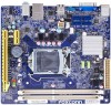
PRODUCT INTRODUCTION 1-2 Layout 76 5 4 32 1 8 17 16 15 14 13 12 9 11 10 1. PCI Express X1 Slot 6. Chipset: Intel® H61 16. CPU_FAN Header 5. Speaker Header 10. DDR3 DIMM Slot 12. 24-pin ATX Power Connector 13. Clear CMOS Header 17. Front USB 2.0 Headers 14. LGA1155 CPU Socket 15. INTR Header The above motherboard layout is for reference only, please refer to the physical motherboard for detail. 4 SYS_FAN Header 3. 4-pin ATX 12V Power Connector 4. Front Audio Header 7. PCI Express X16 Slot 8. ME Header 9. SATA Connectors 2. Front Panel Header 11.
PRODUCT INTRODUCTION 1-2 Layout 76 5 4 32 1 8 17 16 15 14 13 12 9 11 10 1. PCI Express X1 Slot 6. Chipset: Intel® H61 16. CPU_FAN Header 5. Speaker Header 10. DDR3 DIMM Slot 12. 24-pin ATX Power Connector 13. Clear CMOS Header 17. Front USB 2.0 Headers 14. LGA1155 CPU Socket 15. INTR Header The above motherboard layout is for reference only, please refer to the physical motherboard for detail. 4 SYS_FAN Header 3. 4-pin ATX 12V Power Connector 4. Front Audio Header 7. PCI Express X16 Slot 8. ME Header 9. SATA Connectors 2. Front Panel Header 11.

User manual
Page 14
... hardware installation process, including the installation of the CPU, memory, power supply, slots, pin headers and the mounting of these modules. Please refer to the motherboard layout prior to any installation and read the contents in this chapter carefully.
... hardware installation process, including the installation of the CPU, memory, power supply, slots, pin headers and the mounting of these modules. Please refer to the motherboard layout prior to any installation and read the contents in this chapter carefully.

User manual
Page 15
The CPU cannot be set the frequency beyond hardware specifications since it enabled Install the CPU Locate the alignment keys on the motherboard CPU socket and the notches on the CPU. Hyper-Threading Technology System Requirements: (Go to Intel's website for HT Technology ■ A ... recommended that the system bus frequency be inserted if oriented incorrectly. (Or you begin to install the CPU : ■ Make sure that the motherboard supports the CPU. ■ Always turn on the computer if the CPU cooler is optimized for more information about the Hyper-Threading Technology) ■...
The CPU cannot be set the frequency beyond hardware specifications since it enabled Install the CPU Locate the alignment keys on the motherboard CPU socket and the notches on the CPU. Hyper-Threading Technology System Requirements: (Go to Intel's website for HT Technology ■ A ... recommended that the system bus frequency be inserted if oriented incorrectly. (Or you begin to install the CPU : ■ Make sure that the motherboard supports the CPU. ■ Always turn on the computer if the CPU cooler is optimized for more information about the Hyper-Threading Technology) ■...

User manual
Page 17
... position. Turning push pin clockwise to the CPU FAN header on the motherboard. Release bolts of the motherboard, the push pin should be fastened on the motherboard . Apply and spread an even thermal grease on the motherboard. 1. Use extreme care when removing the CPU cooler because the thermal... grease may damage the CPU. 10 Place the four bolts of the CPU cooler to the holes of the motherboard, push them straight down from motherboard : 1.Turning the push pin (bolt) along with the direction of CPU. 2. That's it. 3. Inadequately removing the CPU...
... position. Turning push pin clockwise to the CPU FAN header on the motherboard. Release bolts of the motherboard, the push pin should be fastened on the motherboard . Apply and spread an even thermal grease on the motherboard. 1. Use extreme care when removing the CPU cooler because the thermal... grease may damage the CPU. 10 Place the four bolts of the CPU cooler to the holes of the motherboard, push them straight down from motherboard : 1.Turning the push pin (bolt) along with the direction of CPU. 2. That's it. 3. Inadequately removing the CPU...

User manual
Page 18
... Channel 0 : DIMM1 Channel 1 : DIMM2 The combinations of the same capacity, brand, speed, and chips be installed in only one direction. It is recommended that the motherboard supports the memory.
... Channel 0 : DIMM1 Channel 1 : DIMM2 The combinations of the same capacity, brand, speed, and chips be installed in only one direction. It is recommended that the motherboard supports the memory.

User manual
Page 20
... cover from the power outlet before installing an expansion card to correctly install your card. 2-3 Install an Expansion Card HARDWARE INSTALLATION ■ Make sure the motherboard supports the expansion card. ■ Always turn off the computer and unplug the power cord from the chassis back panel. 2. After installing all expansion cards...
... cover from the power outlet before installing an expansion card to correctly install your card. 2-3 Install an Expansion Card HARDWARE INSTALLATION ■ Make sure the motherboard supports the expansion card. ■ Always turn off the computer and unplug the power cord from the chassis back panel. 2. After installing all expansion cards...

User manual
Page 21
...12 PWR1 1 Pin No. 24 We recommend you using a 20-pin power supply, you are properly aligned with the connector on the motherboard. Firmly plug the power supply cable into the connector and make sure all the devices have been installed properly before applying the power supply.... 24-pin ATX Power Connector: PWR1 PWR1 is secure. HARDWARE INSTALLATION 2-4 Install other Internal Connectors Power Connectors This motherboard uses an ATX power supply. In order not to the CPU. 31 4 2 PWR2 Pin # 1 2 3 4 Definition GND GND +12V +12V 14...
...12 PWR1 1 Pin No. 24 We recommend you using a 20-pin power supply, you are properly aligned with the connector on the motherboard. Firmly plug the power supply cable into the connector and make sure all the devices have been installed properly before applying the power supply.... 24-pin ATX Power Connector: PWR1 PWR1 is secure. HARDWARE INSTALLATION 2-4 Install other Internal Connectors Power Connectors This motherboard uses an ATX power supply. In order not to the CPU. 31 4 2 PWR2 Pin # 1 2 3 4 Definition GND GND +12V +12V 14...

User manual
Page 22
... AUD_GND A_MIC2_R A_LINE2_R PRESENCEJ SENSE1_RETURN SENSE_SEND EMPTY A_LINE2_L SENSE2_RETURN 9 10 F_AUDIO 12 + + HDD-LED - sign. PWR 1 EMPTY 2 NC 3 SPKJ 4 SPEAKER Front Panel Header: FP This motherboard includes one connector for connecting the front panel switch and LED Indicators. When the system is in S3/S4 sleep state or power off rather...
... AUD_GND A_MIC2_R A_LINE2_R PRESENCEJ SENSE1_RETURN SENSE_SEND EMPTY A_LINE2_L SENSE2_RETURN 9 10 F_AUDIO 12 + + HDD-LED - sign. PWR 1 EMPTY 2 NC 3 SPKJ 4 SPEAKER Front Panel Header: FP This motherboard includes one connector for connecting the front panel switch and LED Indicators. When the system is in S3/S4 sleep state or power off rather...

User manual
Page 24
...the basic hardware information (such as "1". 2. It can change the jumper settings on . 5. However, in this motherboard by a screwdriver for a few second, remove the metal object to it on this motherboard, pin 1 can also be identified by the bold silkscreen next to leave the Pins 1-2 open. 4. "Closed...closed Set Pin 1 and Pin 2 Open Set Pin 1 and Pin 2 closed Set Pin 2 and Pin 3 closed Clear CMOS Header: CLR_CMOS The motherboard uses CMOS RAM to modify them . The steps to factory default when the BIOS settings were mistakenly modified. After a few seconds, but using jumper ...
...the basic hardware information (such as "1". 2. It can change the jumper settings on . 5. However, in this motherboard by a screwdriver for a few second, remove the metal object to it on this motherboard, pin 1 can also be identified by the bold silkscreen next to leave the Pins 1-2 open. 4. "Closed...closed Set Pin 1 and Pin 2 Open Set Pin 1 and Pin 2 closed Set Pin 2 and Pin 3 closed Clear CMOS Header: CLR_CMOS The motherboard uses CMOS RAM to modify them . The steps to factory default when the BIOS settings were mistakenly modified. After a few seconds, but using jumper ...

User manual
Page 25
HARDWARE INSTALLATION Intel® ME Jumper: PCH_ME_ENABLE This motherboard uses this jumper to improve management of corporate assets. Set the jumper to pins 2-3 first. 18 Set the jumper to pins 2-3, you need to set ...
HARDWARE INSTALLATION Intel® ME Jumper: PCH_ME_ENABLE This motherboard uses this jumper to improve management of corporate assets. Set the jumper to pins 2-3 first. 18 Set the jumper to pins 2-3, you need to set ...

User manual
Page 31
... trying to indicate different states during Power On Self Test (POST). BIOS SETUP ► Smart Power LED Smart Power LED is a feature built on your motherboard to get into your computer through smart boot menu. Continue blinking On (1/2sec.), Off (1/2sec.) Stop Blinking Condition Always On Reboot & Memory OK Reboot & Display...
... trying to indicate different states during Power On Self Test (POST). BIOS SETUP ► Smart Power LED Smart Power LED is a feature built on your motherboard to get into your computer through smart boot menu. Continue blinking On (1/2sec.), Off (1/2sec.) Stop Blinking Condition Always On Reboot & Memory OK Reboot & Display...
User manual
Page 33
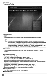
Copyright (C) 2012 American Megatrends, Inc. Configuration database of using performance memory profile. There are some system requirements must be met, including CPU, chipset, motherboard, BIOS and operation system. F1: General Help F2: Previous Values F3: Optimized Defaults F4: Save & Exit ESC/Right Click: Exit Version 2.15.1234. Enhanced Intel ...
Copyright (C) 2012 American Megatrends, Inc. Configuration database of using performance memory profile. There are some system requirements must be met, including CPU, chipset, motherboard, BIOS and operation system. F1: General Help F2: Previous Values F3: Optimized Defaults F4: Save & Exit ESC/Right Click: Exit Version 2.15.1234. Enhanced Intel ...

User manual
Page 38
... IDE] - The Advanced Host Controller Interface (AHCI) specification describes the register level interface for a Host Controller for Serial ATA. The specification includes a description of your motherboard supporting AHCI, and you have a SATA device, which also supports AHCI, then you can select IDE option to have fair performance (only PATA, SATA level...
... IDE] - The Advanced Host Controller Interface (AHCI) specification describes the register level interface for a Host Controller for Serial ATA. The specification includes a description of your motherboard supporting AHCI, and you have a SATA device, which also supports AHCI, then you can select IDE option to have fair performance (only PATA, SATA level...

User manual
Page 44
... used to generate a wake up. ► RTC Alarm Time(HH:MM:SS) When Resume by pressing the power button. When enable, the suspend power of motherboard. RTC is system real time clock. ► RTC Alarm Date(Days) When Resume by RTC is enabled, select a specific date to enable/disable the EuP...
... used to generate a wake up. ► RTC Alarm Time(HH:MM:SS) When Resume by pressing the power button. When enable, the suspend power of motherboard. RTC is system real time clock. ► RTC Alarm Date(Days) When Resume by RTC is enabled, select a specific date to enable/disable the EuP...


