
User manual
Page 6
... Channel Memory Configuration 10 Installing a Memory 11 2-3 Install an Expansion Card 12 2-4 Install other Internal Connectors 13 2-5 Jumpers 16 Chapter 3 BIOS Setup Enter BIOS Setup 19 Main...20 F-center...22 Smart BIOS 22 Fox Intelligent Stepping 23 CPU Configuration 24 Performance Tuning 25 Advanced...27 North Bridge 27 ME Subsystem 28 Onboard Device...
... Channel Memory Configuration 10 Installing a Memory 11 2-3 Install an Expansion Card 12 2-4 Install other Internal Connectors 13 2-5 Jumpers 16 Chapter 3 BIOS Setup Enter BIOS Setup 19 Main...20 F-center...22 Smart BIOS 22 Fox Intelligent Stepping 23 CPU Configuration 24 Performance Tuning 25 Advanced...27 North Bridge 27 ME Subsystem 28 Onboard Device...

User manual
Page 15
... the CPU Socket Notch LGA1155 CPU Pin-1 triangle marking of the CPU. Hyper-Threading Technology System Requirements: (Go to Intel's website for HT Technology ■ A BIOS that supports HT Technology and has it does not meet the standard requirements for the peripherals. It is not recommended that the system bus frequency...
... the CPU Socket Notch LGA1155 CPU Pin-1 triangle marking of the CPU. Hyper-Threading Technology System Requirements: (Go to Intel's website for HT Technology ■ A BIOS that supports HT Technology and has it does not meet the standard requirements for the peripherals. It is not recommended that the system bus frequency...

User manual
Page 20
...and Removing a PCI Express x16 Graphics Card: • Installing a Graphics Card: Gently insert the graphics card into the slot. 4. If necessary, go to BIOS Setup to the chassis back panel with a screw. 5. Make sure the graphics card is fully seated in the slot. 3. Locate an expansion slot that supports... your computer. Secure the card's metal bracket to make any required BIOS changes for your operating system. Turn on your card. Install the driver provided with the slot, and press down on the card are ...
...and Removing a PCI Express x16 Graphics Card: • Installing a Graphics Card: Gently insert the graphics card into the slot. 4. If necessary, go to BIOS Setup to the chassis back panel with a screw. 5. Make sure the graphics card is fully seated in the slot. 3. Locate an expansion slot that supports... your computer. Secure the card's metal bracket to make any required BIOS changes for your operating system. Turn on your card. Install the driver provided with the slot, and press down on the card are ...

User manual
Page 23
... TX+ TXGND RXRX+ GND SATA_1/2/3/4 VCC DD+ GND EMPTY 12 9 10 VCC DD+ GND NC F_USB1/2 The system can be controlled and monitored in the BIOS Setup. The SATA_1/2/3/4 allows up to a security switch on the chassis. If eventually the chassis is used to connect with USB 2.0 specification, you can be...
... TX+ TXGND RXRX+ GND SATA_1/2/3/4 VCC DD+ GND EMPTY 12 9 10 VCC DD+ GND NC F_USB1/2 The system can be controlled and monitored in the BIOS Setup. The SATA_1/2/3/4 allows up to a security switch on the chassis. If eventually the chassis is used to connect with USB 2.0 specification, you can be...

User manual
Page 24
...done by touching two pins by a screwdriver for a few second, remove the metal object to short them . The steps to factory default when the BIOS settings were mistakenly modified. Clear CMOS data is recommended. Plug in next chapter. 1 Normal 2 (Default) 3 1 Clear 2 3 CLR_CMOS CAUTION ...cable before adjusting the jumper settings. ■ Do not clear the CMOS while the system is simply labeled as BIOS data, date, time information, hardware password...etc.). Go to BIOS Setup to configure new system as a screwdriver) onto pins 1-2 to leave the Pins 1-2 open. 4. "Closed...
...done by touching two pins by a screwdriver for a few second, remove the metal object to short them . The steps to factory default when the BIOS settings were mistakenly modified. Clear CMOS data is recommended. Plug in next chapter. 1 Normal 2 (Default) 3 1 Clear 2 3 CLR_CMOS CAUTION ...cable before adjusting the jumper settings. ■ Do not clear the CMOS while the system is simply labeled as BIOS data, date, time information, hardware password...etc.). Go to BIOS Setup to configure new system as a screwdriver) onto pins 1-2 to leave the Pins 1-2 open. 4. "Closed...

User manual
Page 25
...) 3 1 Disable 2 3 PCH_ME_ENABLE Definition 1-2(default) 2-3 Description Set Pin 1 and Pin 2 closed Set Pin 2 and Pin 3 closed Function Enable ME function Disable ME function CAUTION Before flashing BIOS ROM, you need to set ME jumper to pins 1-2, you can enable the Intel® Management Engine function. Intel® Management Engine (ME) is an...
...) 3 1 Disable 2 3 PCH_ME_ENABLE Definition 1-2(default) 2-3 Description Set Pin 1 and Pin 2 closed Set Pin 2 and Pin 3 closed Function Enable ME function Disable ME function CAUTION Before flashing BIOS ROM, you need to set ME jumper to pins 1-2, you can enable the Intel® Management Engine function. Intel® Management Engine (ME) is an...

User manual
Page 26
This chapter includes the following cases occur: 1. An error message appears on the screen during the system Power On Self Test (POST) process. 2. You want to change the default CMOS settings. Chapter 3 BIOS Setup This chapter tells how to change system settings through the BIOS Setup menus. You have to run the Setup Program when the following information : ■ Enter BIOS Setup ■ Main ■ F-Center ■ Advanced ■ Boot ■ Power ■ Health ■ Security ■ Save & Exit Detailed descriptions of the BIOS parameters are also provided.
This chapter includes the following cases occur: 1. An error message appears on the screen during the system Power On Self Test (POST) process. 2. You want to change the default CMOS settings. Chapter 3 BIOS Setup This chapter tells how to change system settings through the BIOS Setup menus. You have to run the Setup Program when the following information : ■ Enter BIOS Setup ■ Main ■ F-Center ■ Advanced ■ Boot ■ Power ■ Health ■ Security ■ Save & Exit Detailed descriptions of the BIOS parameters are also provided.

User manual
Page 27
... explained below: Main It displays the basic system configuration, such as less I /O cards installed. BIOS SETUP Enter BIOS Setup The BIOS is the communication bridge between hardware and software, correctly setting up the BIOS parameters is heavy, set up through this menu. They all can set a password, the system... the system performance can be viewed or set up through this menu. If you to optimal default may offer better performance in the BIOS Setup, and we shall not be responsible for the chipset can be loaded through this menu. You also can be optimized. Use the...
... explained below: Main It displays the basic system configuration, such as less I /O cards installed. BIOS SETUP Enter BIOS Setup The BIOS is the communication bridge between hardware and software, correctly setting up the BIOS parameters is heavy, set up through this menu. They all can set a password, the system... the system performance can be viewed or set up through this menu. If you to optimal default may offer better performance in the BIOS Setup, and we shall not be responsible for the chipset can be loaded through this menu. You also can be optimized. Use the...

User manual
Page 28
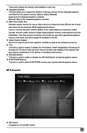
...&Exit System Date System Time Access Level Model Name ME Version BIOS Version Build Date and Time Halt On CPU Brand Name: Genuine Intel(R) CPU @ 2.20GHz Total Memory MAC Address [Mon 01/14/2012] [10:43:34] Administrator H61MD/H61MD-V 8.1.2.1318 CB2F1D02 01/05/2013 16:01:17 [All, but...is detected during [All Errors]: All errors can check this product. ► ME Version It displays the current ME version. ► BIOS Version It displays the current BIOS version. User can result in system halt. 21 to select a field. Use Tab to 31. Date-date from 1 to switch ...
...&Exit System Date System Time Access Level Model Name ME Version BIOS Version Build Date and Time Halt On CPU Brand Name: Genuine Intel(R) CPU @ 2.20GHz Total Memory MAC Address [Mon 01/14/2012] [10:43:34] Administrator H61MD/H61MD-V 8.1.2.1318 CB2F1D02 01/05/2013 16:01:17 [All, but...is detected during [All Errors]: All errors can check this product. ► ME Version It displays the current ME version. ► BIOS Version It displays the current BIOS version. User can result in system halt. 21 to select a field. Use Tab to 31. Date-date from 1 to switch ...

User manual
Page 29
BIOS SETUP [No Errors]: No error can result in system halt. [All, but keyboard]: All errors but keyboard can result in your system before powering on how many memory modules are installed in system halt. ► CPU Brand Name It displays the current CPU name. ► Total Memory This item displays the total memory size. The size is depending on . ► MAC Address This item displays the onboard LAN MAC address. 22
BIOS SETUP [No Errors]: No error can result in system halt. [All, but keyboard]: All errors but keyboard can result in your system before powering on how many memory modules are installed in system halt. ► CPU Brand Name It displays the current CPU name. ► Total Memory This item displays the total memory size. The size is depending on . ► MAC Address This item displays the onboard LAN MAC address. 22

User manual
Page 30
...&Exit Smart Power LED Settings → ←: Select Screen ↑ ↓/Click: Select Item Enter/Dbl Click: Select +/-: Change Opt. F-center BIOS SETUP Main F-center Advanced Boot Fox Control Center Super BIOS Protect ▶ Smart BIOS ▶ Fox Intelligent Stepping ▶ CPU Configuration ▶ Performance Tuning Power Health [Enabled] Security Save&Exit Super...
...&Exit Smart Power LED Settings → ←: Select Screen ↑ ↓/Click: Select Item Enter/Dbl Click: Select +/-: Change Opt. F-center BIOS SETUP Main F-center Advanced Boot Fox Control Center Super BIOS Protect ▶ Smart BIOS ▶ Fox Intelligent Stepping ▶ CPU Configuration ▶ Performance Tuning Power Health [Enabled] Security Save&Exit Super...

User manual
Page 31
... enter smart boot menu. You can significantly reduce the EMI (Electromagnetic Interference) generated by different long-short blinking intervals. Off), one long On (1sec.), continuously. BIOS SETUP ► Smart Power LED Smart Power LED is a feature built on your computer through smart boot menu. System Status Normal No Memory No Display...
... enter smart boot menu. You can significantly reduce the EMI (Electromagnetic Interference) generated by different long-short blinking intervals. Off), one long On (1sec.), continuously. BIOS SETUP ► Smart Power LED Smart Power LED is a feature built on your computer through smart boot menu. System Status Normal No Memory No Display...

User manual
Page 32
... Encryption Standard feature. ► Intel XD Bit This item is used to enable or disable CPU C6 (ACPI C3) report to OS. 25 CPU Configuration BIOS SETUP Main F-center Advanced Boot CPU Configuration CPU Brand Name: Genuine Intel(R) CPU @ 2.20GHz L1 Data Cache L1 Code Cache L2 Cache L3 Cache Processor...
... Encryption Standard feature. ► Intel XD Bit This item is used to enable or disable CPU C6 (ACPI C3) report to OS. 25 CPU Configuration BIOS SETUP Main F-center Advanced Boot CPU Configuration CPU Brand Name: Genuine Intel(R) CPU @ 2.20GHz L1 Data Cache L1 Code Cache L2 Cache L3 Cache Processor...
User manual
Page 33
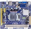
...;: Select Screen ↑ ↓/Click: Select Item Enter/Dbl Click: Select +/-: Change Opt. There are some system requirements must be met, including CPU, chipset, motherboard, BIOS and operation system. Options: [Automatic], [Manual], [XMP Profile 1], [XMP Profile 2]. [Automatic]- The following items appear only when the option is set the memory clock multiplier...
...;: Select Screen ↑ ↓/Click: Select Item Enter/Dbl Click: Select +/-: Change Opt. There are some system requirements must be met, including CPU, chipset, motherboard, BIOS and operation system. Options: [Automatic], [Manual], [XMP Profile 1], [XMP Profile 2]. [Automatic]- The following items appear only when the option is set the memory clock multiplier...

User manual
Page 34
BIOS SETUP This item is used to set the graphics voltage. 27 The target clock frequency is determined from the supported CAS latencies at given clock ...; Graphics Core Ratio Limit This item is used to return data after the read CAS_L isasserted depends on the memory clock frequency. The value that BIOS programs into the memory controller is used to set the graphics care ratio limit. ► Graphics Voltage(1/256) This item is a function of memory clocks...
BIOS SETUP This item is used to set the graphics voltage. 27 The target clock frequency is determined from the supported CAS latencies at given clock ...; Graphics Core Ratio Limit This item is used to return data after the read CAS_L isasserted depends on the memory clock frequency. The value that BIOS programs into the memory controller is used to set the graphics care ratio limit. ► Graphics Voltage(1/256) This item is a function of memory clocks...

User manual
Page 35
... (C) 2012 American Megatrends, Inc. ► North Bridge/ME Subsystem/Onboard Device Configuration/SATA Configuration /Super IO Configuration/Network Stack Press to go to its submenu. BIOS SETUP Advanced Main F-center Advanced Boot ▶ North Bridge ▶ ME Subsystem ▶ Onboard Device Configuration ▶ SATA Configuration ▶ Super IO Configuration ▶ Network...
... (C) 2012 American Megatrends, Inc. ► North Bridge/ME Subsystem/Onboard Device Configuration/SATA Configuration /Super IO Configuration/Network Stack Press to go to its submenu. BIOS SETUP Advanced Main F-center Advanced Boot ▶ North Bridge ▶ ME Subsystem ▶ Onboard Device Configuration ▶ SATA Configuration ▶ Super IO Configuration ▶ Network...
User manual
Page 36
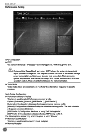
... is used by internal graphics device. F1: General Help F2: Previous Values F3: Optimized Defaults F4: Save & Exit ESC/Right Click: Exit Version 2.15.1234. BIOS SETUP These items display the memory size installed on each slot. ► Integrated Graphics This item allows you to determine whether to allocate memory for...
... is used by internal graphics device. F1: General Help F2: Previous Values F3: Optimized Defaults F4: Save & Exit ESC/Right Click: Exit Version 2.15.1234. BIOS SETUP These items display the memory size installed on each slot. ► Integrated Graphics This item allows you to determine whether to allocate memory for...

User manual
Page 37
... enable the support for EFI applications. ► Azalia HD Audio controller This item is used to enable or disable the Azalia HD Audio Controller. 30 BIOS SETUP Onboard Device Configuration Main F-center Advanced Boot Power Health Security Save&Exit Onboard Device Configuration Onboard LAN Controller Onboard USB Controller Legacy USB Support...
... enable the support for EFI applications. ► Azalia HD Audio controller This item is used to enable or disable the Azalia HD Audio Controller. 30 BIOS SETUP Onboard Device Configuration Main F-center Advanced Boot Power Health Security Save&Exit Onboard Device Configuration Onboard LAN Controller Onboard USB Controller Legacy USB Support...

User manual
Page 38
... native IDE mode. [AHCI] - F1: General Help F2: Previous Values F3: Optimized Defaults F4: Save & Exit ESC/Right Click: Exit Version 2.15.1234. SATA Configuration BIOS SETUP Main F-center Advanced Boot Power Health Security Save&Exit SATA Configuration Onboard SATA Controller Onboard SATA Mode ▶ SATA Port1: Not Present ▶ SATA...
... native IDE mode. [AHCI] - F1: General Help F2: Previous Values F3: Optimized Defaults F4: Save & Exit ESC/Right Click: Exit Version 2.15.1234. SATA Configuration BIOS SETUP Main F-center Advanced Boot Power Health Security Save&Exit SATA Configuration Onboard SATA Controller Onboard SATA Mode ▶ SATA Port1: Not Present ▶ SATA...

User manual
Page 39
F1: General Help F2: Previous Values F3: Optimized Defaults F4: Save & Exit ESC/Right Click: Exit Version 2.15.1234. BIOS SETUP Super IO Configuration Main F-center Advanced Boot Super IO Configuration Super IO Chip Power Health IT8772E Security Save&Exit Set Parameters of Serial Port 1 (COMA) → ←: Select Screen ↑ ↓/Click: Select Item Enter/Dbl Click: Select +/-: Change Opt. Copyright (C) 2012 American Megatrends, Inc. 32
F1: General Help F2: Previous Values F3: Optimized Defaults F4: Save & Exit ESC/Right Click: Exit Version 2.15.1234. BIOS SETUP Super IO Configuration Main F-center Advanced Boot Super IO Configuration Super IO Chip Power Health IT8772E Security Save&Exit Set Parameters of Serial Port 1 (COMA) → ←: Select Screen ↑ ↓/Click: Select Item Enter/Dbl Click: Select +/-: Change Opt. Copyright (C) 2012 American Megatrends, Inc. 32


