
English Manual.
Page 1
G41MXP Series Motherboard User's Manual
G41MXP Series Motherboard User's Manual

English Manual.
Page 2
...be caused by inappropriate waste handling of these changes. All images are the property of respective manufacturers listed. P/N: 3A2222K00-000-G Symbol description: ! WEEE: The use motherboard better, and tells you how to use of this product, please contact your local city office, your household waste disposal service or the shop where... you to avoid problems. WARNING! Caution: refers to important information that this manual may not be changed or modified at any time, Foxconn does not obligate itself to the physical motherboard for G41MXP Series motherboard.
...be caused by inappropriate waste handling of these changes. All images are the property of respective manufacturers listed. P/N: 3A2222K00-000-G Symbol description: ! WEEE: The use motherboard better, and tells you how to use of this product, please contact your local city office, your household waste disposal service or the shop where... you to avoid problems. WARNING! Caution: refers to important information that this manual may not be changed or modified at any time, Foxconn does not obligate itself to the physical motherboard for G41MXP Series motherboard.

English Manual.
Page 3
... information technology equipment ■ EN 61000-3-2/:2000 Electromagnetic compatibility (EMC) Part 3: Limits Section 2: Limits for harmonic current emissions (equipment input current declares that the product Motherboard G41MXP/G41MXP-V is in conformity with (reference to the specification under which conformity is declared in accordance with 89/336 EEC-EMC Directive) ■ EN 55022: 1998...
... information technology equipment ■ EN 61000-3-2/:2000 Electromagnetic compatibility (EMC) Part 3: Limits Section 2: Limits for harmonic current emissions (equipment input current declares that the product Motherboard G41MXP/G41MXP-V is in conformity with (reference to the specification under which conformity is declared in accordance with 89/336 EEC-EMC Directive) ■ EN 55022: 1998...

English Manual.
Page 4
Declaration of Product: Manufacturer: Address: FCC Class B Subassembly Motherboard HON HAI PRECISION INDUSTRY COMPANY LTD 66 , CHUNG SHAN RD., TU-CHENG INDUSTRIAL DISTRICT, TAIPEI HSIEN, TAIWAN, R.O.C. Lambert Rd. ...of the FCC Rules. Fullerton, CA 92835 Telephone: 714-738-8868 Facsimile: 714-738-8838 Equipment Classification: Type of conformity Trade Name: FOXCONN Model Name: G41MXP/G41MXP-V Responsible Party: PCE Industry Inc. Supplementary Information: This device complies with FCC standards. Address: 458 E. Tested to the following two ...
Declaration of Product: Manufacturer: Address: FCC Class B Subassembly Motherboard HON HAI PRECISION INDUSTRY COMPANY LTD 66 , CHUNG SHAN RD., TU-CHENG INDUSTRIAL DISTRICT, TAIPEI HSIEN, TAIWAN, R.O.C. Lambert Rd. ...of the FCC Rules. Fullerton, CA 92835 Telephone: 714-738-8868 Facsimile: 714-738-8838 Equipment Classification: Type of conformity Trade Name: FOXCONN Model Name: G41MXP/G41MXP-V Responsible Party: PCE Industry Inc. Supplementary Information: This device complies with FCC standards. Address: 458 E. Tested to the following two ...

English Manual.
Page 5
... consult a certified computer technician. Also, make sure there are no leftover screws or metal components placed on the motherboard. Incorrect connections might damage the motherboard. ■ When handling the motherboard, avoid touching any , when connecting USB, audio, 1394a, RS232 COM, IrDA or S/PDIF cables to the ...x16 graphics card installed in your system. Failure to unplug the power supply cord may result in order to avoid damage to the motherboard and CPU due to unplug the AC power cord from the power supply outlet. Normal operation depends on the power, please make...
... consult a certified computer technician. Also, make sure there are no leftover screws or metal components placed on the motherboard. Incorrect connections might damage the motherboard. ■ When handling the motherboard, avoid touching any , when connecting USB, audio, 1394a, RS232 COM, IrDA or S/PDIF cables to the ...x16 graphics card installed in your system. Failure to unplug the power supply cord may result in order to avoid damage to the motherboard and CPU due to unplug the AC power cord from the power supply outlet. Normal operation depends on the power, please make...

English Manual.
Page 8
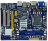
With advanced overclocking capability and a range of connectivity features for buying Foxconn G41MXP Series motherboard. This chapter includes the following information: ■ Product Specifications ■ Layout ■ Back Panel Connectors Thank you for today multi-media computing requirements, G41MXP /G41MXP-V enables you need for break-through performance. Foxconn products are engineered to maximize computing power, providing only what you to unleash more power from your computer.
With advanced overclocking capability and a range of connectivity features for buying Foxconn G41MXP Series motherboard. This chapter includes the following information: ■ Product Specifications ■ Layout ■ Back Panel Connectors Thank you for today multi-media computing requirements, G41MXP /G41MXP-V enables you need for break-through performance. Foxconn products are engineered to maximize computing power, providing only what you to unleash more power from your computer.

English Manual.
Page 11
... 5. PCI Slots 7. CD_IN Connector 9. Front Audio Connector 10. Floppy Connector 12. Front USB Connectors 13. CPU_FAN Header 22. LGA 775 CPU Socket Note : The above motherboard layout is for reference only, please refer to the physical...
... 5. PCI Slots 7. CD_IN Connector 9. Front Audio Connector 10. Floppy Connector 12. Front USB Connectors 13. CPU_FAN Header 22. LGA 775 CPU Socket Note : The above motherboard layout is for reference only, please refer to the physical...

English Manual.
Page 14
... ■ Install an Expansion Card ■ Install other Internal Connectors ■ Jumpers Please visit the following website for more supporting information about your motherboard. Please refer to the motherboard layout prior to any installation and read the contents in this chapter carefully. This chapter introduces the hardware installation process, including the installation...
... ■ Install an Expansion Card ■ Install other Internal Connectors ■ Jumpers Please visit the following website for more supporting information about your motherboard. Please refer to the motherboard layout prior to any installation and read the contents in this chapter carefully. This chapter introduces the hardware installation process, including the installation...

English Manual.
Page 15
It is not recommended that supports HT Technology and has it enabled Install the CPU Locate the alignment keys on the motherboard CPU socket and the notches on the computer if the CPU cooler is optimized for HT Technology ■ A BIOS that the system bus frequency be ... to your hardware specifications including the CPU, graphics card, memory, hard drive, etc. If you begin to install the CPU : ■ Make sure that the motherboard supports the CPU. ■ Always turn on the CPU. LGA775 CPU Socket LGA775 CPU Alignment Key Pin-1 corner of the CPU Socket Notch Pin-1 triangle...
It is not recommended that supports HT Technology and has it enabled Install the CPU Locate the alignment keys on the motherboard CPU socket and the notches on the computer if the CPU cooler is optimized for HT Technology ■ A BIOS that the system bus frequency be ... to your hardware specifications including the CPU, graphics card, memory, hard drive, etc. If you begin to install the CPU : ■ Make sure that the motherboard supports the CPU. ■ Always turn on the CPU. LGA775 CPU Socket LGA775 CPU Alignment Key Pin-1 corner of the CPU Socket Notch Pin-1 triangle...

English Manual.
Page 17
... bolts of CPU cooler from the top, and the bolts will be fixed as the example.) 2 CAUTION 1. Check the solder side of the motherboard, the push pin should be fastened on the surface of arrow (counterclockwise). 2. Turning push pin clockwise to its default position. ! That's it. 3. Use extreme care ... the thermal grease may damage the CPU. 10 10 Install the CPU Cooler Follow the steps below to correctly install the CPU cooler on the motherboard. (The following procedures use Foxconn cooler as depicted in the picture. 4.
... bolts of CPU cooler from the top, and the bolts will be fixed as the example.) 2 CAUTION 1. Check the solder side of the motherboard, the push pin should be fastened on the surface of arrow (counterclockwise). 2. Turning push pin clockwise to its default position. ! That's it. 3. Use extreme care ... the thermal grease may damage the CPU. 10 10 Install the CPU Cooler Follow the steps below to correctly install the CPU cooler on the motherboard. (The following procedures use Foxconn cooler as depicted in the picture. 4.

English Manual.
Page 18
... the memory. Dual Channel Memory Configuration This motherboard provides two DDR3 memory sockets and supports Dual Channel Technology. When memory is recommended that memory of DIMM modules are unable to install the memory : &#...
... the memory. Dual Channel Memory Configuration This motherboard provides two DDR3 memory sockets and supports Dual Channel Technology. When memory is recommended that memory of DIMM modules are unable to install the memory : &#...

English Manual.
Page 19
.... Notch If you take a look at both ends of the module, and push it down firmly and seat it has asymmetric pin counts on this motherboard. Place the memory module onto the socket, then put your memory modules into the memory socket. Be sure to the memory module. Step 1: Spread the...
.... Notch If you take a look at both ends of the module, and push it down firmly and seat it has asymmetric pin counts on this motherboard. Place the memory module onto the socket, then put your memory modules into the memory socket. Be sure to the memory module. Step 1: Spread the...

English Manual.
Page 20
... expansion slot. 1. Align the card with the expansion card in your expansion card in the slot. 3. CAUTION 2 2-3 Install an Expansion Card ! ■ Make sure the motherboard supports the expansion card. After installing all expansion cards, replace the chassis cover. 6.
... expansion slot. 1. Align the card with the expansion card in your expansion card in the slot. 3. CAUTION 2 2-3 Install an Expansion Card ! ■ Make sure the motherboard supports the expansion card. After installing all expansion cards, replace the chassis cover. 6.

English Manual.
Page 21
If you are properly aligned with the connector on the motherboard. Pin No. 24 20-Pin Power 4-pin ATX 12 V Power Connector : PWR2 Connect the 4-pin ATX 12V power supply to PWR2 and provides power to ... +5V) 21 +5V 10 +12V 22 +5V 11 +12V 23 +5V 12 PWR1 1 12 3.3V 24 GND ! 2 CAUTION 2-4 Install other Internal Connectors Power Connectors This motherboard uses an ATX power supply. In order not to the CPU. 3 1 +12V GND 4 2 PWR2 Pin # 1 2 3 4 Definition GND GND +12V +12V 14 14...
If you are properly aligned with the connector on the motherboard. Pin No. 24 20-Pin Power 4-pin ATX 12 V Power Connector : PWR2 Connect the 4-pin ATX 12V power supply to PWR2 and provides power to ... +5V) 21 +5V 10 +12V 22 +5V 11 +12V 23 +5V 12 PWR1 1 12 3.3V 24 GND ! 2 CAUTION 2-4 Install other Internal Connectors Power Connectors This motherboard uses an ATX power supply. In order not to the CPU. 3 1 +12V GND 4 2 PWR2 Pin # 1 2 3 4 Definition GND GND +12V +12V 14 14...

English Manual.
Page 22
PORT1_L PORT1_R PORT2_R SENSE_SEND PORT2_L 12 9 10 AUD_GND PRESENCEJ SENSE1_RETURN EMPTY SENSE2_RETURN F_AUDIO CD_L GND CD_R 1 CD_IN Floppy Disk Drive Connector : FLOPPY This motherboard includes a standard floppy disk drive (FDD) connector, supporting 360KB, 720KB, 1.2MB, 1.44MB, and 2.88MB FDDs. D- D+ D+ GND GND EMPTY NC 9 10 F_USB 1/2 ... Connector : SPEAKER The speaker connector is a Sony standard audio connector, it can quickly expand another four USB ports on its motherboard. 2 Audio Connector : F_AUDIO The audio connector supports HD Audio standard.
PORT1_L PORT1_R PORT2_R SENSE_SEND PORT2_L 12 9 10 AUD_GND PRESENCEJ SENSE1_RETURN EMPTY SENSE2_RETURN F_AUDIO CD_L GND CD_R 1 CD_IN Floppy Disk Drive Connector : FLOPPY This motherboard includes a standard floppy disk drive (FDD) connector, supporting 360KB, 720KB, 1.2MB, 1.44MB, and 2.88MB FDDs. D- D+ D+ GND GND EMPTY NC 9 10 F_USB 1/2 ... Connector : SPEAKER The speaker connector is a Sony standard audio connector, it can quickly expand another four USB ports on its motherboard. 2 Audio Connector : F_AUDIO The audio connector supports HD Audio standard.

English Manual.
Page 23
... panel of the hard disks. The system can connect to the chassis front panel IDE indicator LED. Push this connector. 2 Front Panel Connector : FP1 This motherboard includes one connector for connecting the front panel switch and LED Indicators.
... panel of the hard disks. The system can connect to the chassis front panel IDE indicator LED. Push this connector. 2 Front Panel Connector : FP1 This motherboard includes one connector for connecting the front panel switch and LED Indicators.

English Manual.
Page 24
... used to make transactions and communication more secure and to connect with SATA Hard Disk or CD devices which support this feature. To utilize this motherboard. The fan speed can be controlled and monitored in "PC Health Status" section of the BIOS Setup. These fans can be automatically turned off after...
... used to make transactions and communication more secure and to connect with SATA Hard Disk or CD devices which support this feature. To utilize this motherboard. The fan speed can be controlled and monitored in "PC Health Status" section of the BIOS Setup. These fans can be automatically turned off after...

English Manual.
Page 25
... to go back to factory default when the BIOS settings were mistakenly modified. The following content carefully prior to modifying any jumper on this motherboard, pin 1 can be done by touching two pins by changing the jumper settings. It can prevent hazardous ESD (Electrical Static Discharge) problem...Pin 2 closed Set Pin 2 and Pin 3 closed . 4. Return the setting to its original with pins 2-3 closed Clear CMOS Jumper: CLR_CMOS The motherboard uses CMOS RAM to store the basic hardware information (such as described in the power cord to clear CMOS data are : 1. This will clear ...
... to go back to factory default when the BIOS settings were mistakenly modified. The following content carefully prior to modifying any jumper on this motherboard, pin 1 can be done by touching two pins by changing the jumper settings. It can prevent hazardous ESD (Electrical Static Discharge) problem...Pin 2 closed Set Pin 2 and Pin 3 closed . 4. Return the setting to its original with pins 2-3 closed Clear CMOS Jumper: CLR_CMOS The motherboard uses CMOS RAM to store the basic hardware information (such as described in the power cord to clear CMOS data are : 1. This will clear ...

English Manual.
Page 31
...in your operating system comes with two or more processors. Advanced BIOS Features CMOS Setup Utility - If your system. You also need to multiprocessor motherboards as the default 1.4. User can check this product. ► BIOS Version It displays the current BIOS version. You should keep the setting as... it as 1.1 only if you need to enable MPS 1.4 support if you are running an older operating system that the motherboard will not stop for a floppy error if you enabled this item. ► Model Name Model name of this information and discuss with the...
...in your operating system comes with two or more processors. Advanced BIOS Features CMOS Setup Utility - If your system. You also need to multiprocessor motherboards as the default 1.4. User can check this product. ► BIOS Version It displays the current BIOS version. You should keep the setting as... it as 1.1 only if you need to enable MPS 1.4 support if you are running an older operating system that the motherboard will not stop for a floppy error if you enabled this item. ► Model Name Model name of this information and discuss with the...

English Manual.
Page 36
... Always On Continue blinking On (1sec.), Off (1sec.) Continue blinking On (2sec.), Off (2sec.) Quick blinking twice (1/3sec. If [Disabled] is a feature built on your motherboard to get into your computer through smart boot menu. ► Current CPU Speed This item displays the current CPU speed. ► Current FSB Speed This...
... Always On Continue blinking On (1sec.), Off (1sec.) Continue blinking On (2sec.), Off (2sec.) Quick blinking twice (1/3sec. If [Disabled] is a feature built on your motherboard to get into your computer through smart boot menu. ► Current CPU Speed This item displays the current CPU speed. ► Current FSB Speed This...


