English Manual.
Page 6
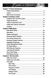
... Install the Memory 10 Install an Expansion Card 12 Install other Internal Connectors 13 Jumpers 17 Chapter 3 BIOS Setup Enter BIOS Setup 20 Main Menu 20 System Information 22 Advanced BIOS Features 24 Fox Central Control Unit 26 Advanced Chipset Features 30 Integrated Peripherals 36 Power Management Setup 40... PC Health Status 42 BIOS Security Features 43 Load Optimal Defaults 44 Save & Exit Setup 44 Exit Without Saving 44 Chapter 4 CD Instruction Utility CD ...
... Install the Memory 10 Install an Expansion Card 12 Install other Internal Connectors 13 Jumpers 17 Chapter 3 BIOS Setup Enter BIOS Setup 20 Main Menu 20 System Information 22 Advanced BIOS Features 24 Fox Central Control Unit 26 Advanced Chipset Features 30 Integrated Peripherals 36 Power Management Setup 40... PC Health Status 42 BIOS Security Features 43 Load Optimal Defaults 44 Save & Exit Setup 44 Exit Without Saving 44 Chapter 4 CD Instruction Utility CD ...

English Manual.
Page 7
...67 FOX LOGO 68 FOX DMI 69 Chapter 5 RAID Configuration RAID Configuration Introduction 72 FastBuild Driver 74 Create a RAID Driver Diskette 76 RAID Enable in BIOS 78 Select a RAID Array for Use 78 Install a New Windows XP 91 Setting Up a Non-Bootable RAID Array 95 Technical Support : Website ...com Support Support Website : http://www.foxconnchannel.com/support/online.aspx or http://www.foxconnsupport.com Worldwide E-mail Support : pcebg-cisg-support@foxconn.com CPU, Memory, VGA Compatibility Supporting Website : http://www.foxconnchannel.com/product/Motherboards/compatibility.aspx
...67 FOX LOGO 68 FOX DMI 69 Chapter 5 RAID Configuration RAID Configuration Introduction 72 FastBuild Driver 74 Create a RAID Driver Diskette 76 RAID Enable in BIOS 78 Select a RAID Array for Use 78 Install a New Windows XP 91 Setting Up a Non-Bootable RAID Array 95 Technical Support : Website ...com Support Support Website : http://www.foxconnchannel.com/support/online.aspx or http://www.foxconnsupport.com Worldwide E-mail Support : pcebg-cisg-support@foxconn.com CPU, Memory, VGA Compatibility Supporting Website : http://www.foxconnchannel.com/product/Motherboards/compatibility.aspx
English Manual.
Page 17
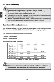
... two channels : Channel 0 : DIMM1, DIMM3 Channel 1 : DIMM2, DIMM4 The combinations of DIMM modules are unable to achieve optimum performance. CAUTION 10 It is installed, the BIOS will automatically check the memory in only one direction. 2 CAUTION 2-2 Install the Memory ! DS/SS Single Channel -
... two channels : Channel 0 : DIMM1, DIMM3 Channel 1 : DIMM2, DIMM4 The combinations of DIMM modules are unable to achieve optimum performance. CAUTION 10 It is installed, the BIOS will automatically check the memory in only one direction. 2 CAUTION 2-2 Install the Memory ! DS/SS Single Channel -
English Manual.
Page 19
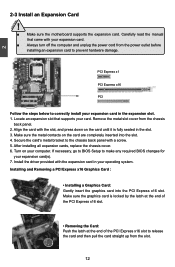
Make sure the metal contacts on your expansion card in the expansion slot. 1. If necessary, go to BIOS Setup to correctly install your computer. Install the driver provided with your card. Carefully read the manual that supports your expansion card. ■ Always turn ... outlet before installing an expansion card to prevent hardware damage. PCI Express x1 PCI Express x16 PCI Follow the steps below to make any required BIOS changes for your operating system. Remove the metal slot cover from the slot. 12 Secure the card's metal bracket to release the card and then...
Make sure the metal contacts on your expansion card in the expansion slot. 1. If necessary, go to BIOS Setup to correctly install your computer. Install the driver provided with your card. Carefully read the manual that supports your expansion card. ■ Always turn ... outlet before installing an expansion card to prevent hardware damage. PCI Express x1 PCI Express x16 PCI Follow the steps below to make any required BIOS changes for your operating system. Remove the metal slot cover from the slot. 12 Secure the card's metal bracket to release the card and then...

English Manual.
Page 23
.... If eventually the chassis was closed, the system will send a message out. The fan speed can detect the chassis intrusion through the function of the BIOS Setup. The system can be automatically turned off after the system enters S3, S4 and S5 sleeping states. 1 GND POWER SENSE CONTROL CPU_FAN / SYS_FAN 16...
.... If eventually the chassis was closed, the system will send a message out. The fan speed can detect the chassis intrusion through the function of the BIOS Setup. The system can be automatically turned off after the system enters S3, S4 and S5 sleeping states. 1 GND POWER SENSE CONTROL CPU_FAN / SYS_FAN 16...
English Manual.
Page 24
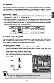
...The steps to it on . 17 "Closed" means placing a jumper cap on this manual, pin 1 is turned on . 5. Go to BIOS Setup to temporarily short them . The shorting can be done by touching two pins by a screwdriver for a few seconds, but using jumper cap... "1". 2. Return the setting to its original with pins 2-3 closed Clear CMOS Jumper: CLR_CMOS The motherboard uses CMOS RAM to factory default when the BIOS settings were mistakenly modified. 2 2-5 Jumpers For some features needed, users can prevent hazardous ESD (Electrical Static Discharge) problem. However, in next chapter...
...The steps to it on . 17 "Closed" means placing a jumper cap on this manual, pin 1 is turned on . 5. Go to BIOS Setup to temporarily short them . The shorting can be done by touching two pins by a screwdriver for a few seconds, but using jumper cap... "1". 2. Return the setting to its original with pins 2-3 closed Clear CMOS Jumper: CLR_CMOS The motherboard uses CMOS RAM to factory default when the BIOS settings were mistakenly modified. 2 2-5 Jumpers For some features needed, users can prevent hazardous ESD (Electrical Static Discharge) problem. However, in next chapter...

English Manual.
Page 25
... using the connected USB devices. 2. At the same time, a corresponding setting must not exceed the power supply capability (+5VSB) whether under normal condition or in BIOS as below: Set -> "Power Management Setup" -> "Resume by USB Devices" to wake up Jumpers: USBPWR1 / 2 / 3 1. otherwise, the system will not power up. ■ The total...
... using the connected USB devices. 2. At the same time, a corresponding setting must not exceed the power supply capability (+5VSB) whether under normal condition or in BIOS as below: Set -> "Power Management Setup" -> "Resume by USB Devices" to wake up Jumpers: USBPWR1 / 2 / 3 1. otherwise, the system will not power up. ■ The total...

English Manual.
Page 26
...) process. 2. You want to change the default CMOS settings. Detailed descriptions of this manual will remain consistent with the newly released BIOS at any given time in this manual is for updated manual if it is available. You have to run the Setup Program when ...the following information : ■ Enter BIOS Setup ■ Main Menu ■ System Information ■ Advanced BIOS Features ■ Fox Central Control Unit ■ Advanced Chipset Features ■ Integrated Peripherals ■ Power Management Setup...
...) process. 2. You want to change the default CMOS settings. Detailed descriptions of this manual will remain consistent with the newly released BIOS at any given time in this manual is for updated manual if it is available. You have to run the Setup Program when ...the following information : ■ Enter BIOS Setup ■ Main Menu ■ System Information ■ Advanced BIOS Features ■ Fox Central Control Unit ■ Advanced Chipset Features ■ Integrated Peripherals ■ Power Management Setup...

English Manual.
Page 27
... through this menu. Copyright (C) 1985-2006, American Megatrends, Inc. ► System Information ► PC Health Status ► Advanced BIOS Features ► BIOS Security Features ► Fox Central Control Unit Load Optimal Defaults ► Advanced Chipset Features Save & Exit Setup ► Integrated Peripherals ... such as Serial I/O and other USB devices... They all can be viewed or set up through this menu. ► Advanced BIOS Features The advanced system features can be set up through this menu. There are boot up settings. ► Fox Central Control ...
... through this menu. Copyright (C) 1985-2006, American Megatrends, Inc. ► System Information ► PC Health Status ► Advanced BIOS Features ► BIOS Security Features ► Fox Central Control Unit Load Optimal Defaults ► Advanced Chipset Features Save & Exit Setup ► Integrated Peripherals ... such as Serial I/O and other USB devices... They all can be viewed or set up through this menu. ► Advanced BIOS Features The advanced system features can be set up through this menu. There are boot up settings. ► Fox Central Control ...
English Manual.
Page 28
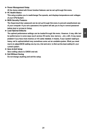
What you need now is to adjust BIOS setting one by one, trial and error, to find out the best setting for your system loading is heavy, set to optimal default may cause ... to Setup. ► Load Optimal Defaults The optimal performance settings can be loaded through this menu to prevent unauthorized use of your CPU/System. ► BIOS Security Features The Supervisor/User password can be set up through this menu. If you set a password, the system will ask you to key in...
What you need now is to adjust BIOS setting one by one, trial and error, to find out the best setting for your system loading is heavy, set to optimal default may cause ... to Setup. ► Load Optimal Defaults The optimal performance settings can be loaded through this menu to prevent unauthorized use of your CPU/System. ► BIOS Security Features The Supervisor/User password can be set up through this menu. If you set a password, the system will ask you to key in...

English Manual.
Page 29
... [Not Detected] Floppy A Halt On Keyboard Mouse Floppy [1.44 MB 31/2] [All Errors, But ...] [Disabled] [Disabled] [Disabled] Model Name BIOS ID : A7GM-S : 799F1D15 Move Enter:Select +/-/:Value F10:Save ESC:Exit F1:General Help F9:Optimized Defaults ► Date (mm:dd:yy) format. Use ... 12. The three fields of the setting are : : respectively. ► Primary/Secondary/Third/Fourth IDE Master/Slave While entering setup, BIOS automatically detects the presence of IDE devices. Please refer to mapping table in next page. ► Floppy A This option allows you to...
... [Not Detected] Floppy A Halt On Keyboard Mouse Floppy [1.44 MB 31/2] [All Errors, But ...] [Disabled] [Disabled] [Disabled] Model Name BIOS ID : A7GM-S : 799F1D15 Move Enter:Select +/-/:Value F10:Save ESC:Exit F1:General Help F9:Optimized Defaults ► Date (mm:dd:yy) format. Use ... 12. The three fields of the setting are : : respectively. ► Primary/Secondary/Third/Fourth IDE Master/Slave While entering setup, BIOS automatically detects the presence of IDE devices. Please refer to mapping table in next page. ► Floppy A This option allows you to...

English Manual.
Page 30
... stop for a floppy error if you enabled this item. ► Model Name Model name of this information and discuss with the field service people if a BIOS upgrade is depending on how many memory modules were installed in your system before powering on. ► MAC Address This item shows the onboard LAN... as SATA as Secondary Primary Secondary Primary SATA as SATA as Secondary Primary Primary IDE Master IDE0 SATA 5 IDE0 - User can check this product. ► BIOS ID / BIOS Version It displays the current...
... stop for a floppy error if you enabled this item. ► Model Name Model name of this information and discuss with the field service people if a BIOS upgrade is depending on how many memory modules were installed in your system before powering on. ► MAC Address This item shows the onboard LAN... as SATA as Secondary Primary Secondary Primary SATA as SATA as Secondary Primary Primary IDE Master IDE0 SATA 5 IDE0 - User can check this product. ► BIOS ID / BIOS Version It displays the current...

English Manual.
Page 31
..., 96, 128, 160, 192, 224, 248. Higher values will skip it as too much time may not agree with a PCI bridge. Advanced BIOS Features CMOS Setup Utility - Advanced BIOS Features IDE Detect Time Out MPS Revision PCI Latency Timer Quiet Boot Quick Boot Bootup Num-Lock Floppy Drive Seek ► Boot Device...
..., 96, 128, 160, 192, 224, 248. Higher values will skip it as too much time may not agree with a PCI bridge. Advanced BIOS Features CMOS Setup Utility - Advanced BIOS Features IDE Detect Time Out MPS Revision PCI Latency Timer Quiet Boot Quick Boot Bootup Num-Lock Floppy Drive Seek ► Boot Device...

English Manual.
Page 32
... is started. 3 [Disabled] : Displays the normal POST messages. [Enabled] : Displays OEM customer logo instead of POST messages. ► Quick Boot While Enabled, this option allows BIOS to skip certain tests while booting, this will shorten the time needed to boot the system. ► Bootup Num-Lock This item defines if the... priority sequence from available CD/DVD drives. 25 The available settings are: On (default) and Off. ► Floppy Drive Seek This item controls whether the BIOS will appear an error message.
... is started. 3 [Disabled] : Displays the normal POST messages. [Enabled] : Displays OEM customer logo instead of POST messages. ► Quick Boot While Enabled, this option allows BIOS to skip certain tests while booting, this will shorten the time needed to boot the system. ► Bootup Num-Lock This item defines if the... priority sequence from available CD/DVD drives. 25 The available settings are: On (default) and Off. ► Floppy Drive Seek This item controls whether the BIOS will appear an error message.

English Manual.
Page 33
... Copyright (C) 1985-2006, American Megatrends, Inc. Copyright (C) 1985-2006, American Megatrends, Inc. Fox Central Control Unit Super BIOS Protect Auto Detect PCI Clock ► Smart BIOS ► Fox Intelligent Stepping ► Voltage Options ► CPU Configuration [Disabled] Help Item [Disabled] [Press Enter] ... Help F9:Optimized Defaults 26 CIH. ► Auto Detect PCI Clock This option is a BIOS write-protection mechanism provided. Super BIOS Protect function protects your BIOS from virus attack, there is used to its submenu. When enabled, the system will turn ...
... Copyright (C) 1985-2006, American Megatrends, Inc. Copyright (C) 1985-2006, American Megatrends, Inc. Fox Central Control Unit Super BIOS Protect Auto Detect PCI Clock ► Smart BIOS ► Fox Intelligent Stepping ► Voltage Options ► CPU Configuration [Disabled] Help Item [Disabled] [Press Enter] ... Help F9:Optimized Defaults 26 CIH. ► Auto Detect PCI Clock This option is a BIOS write-protection mechanism provided. Super BIOS Protect function protects your BIOS from virus attack, there is used to its submenu. When enabled, the system will turn ...
English Manual.
Page 38
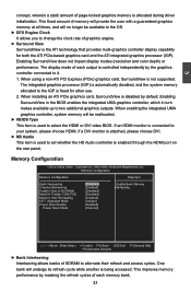
... bank will no longer be reallocated. ► VBIOS Type This item is used to select the HDMI or DVI video BIOS. Enabling SurroundView does not impact display modes (resolution and color depth) or performance. Memory Configuration Memory Configuration Help Item Bank...Channel Interleaving [Enabled] Interleaving Enable Clock to it. 1. Copyright (C) 1985-2006, American Megatrends, Inc. Enabling SurroundView in the BIOS enables the integrated UMA graphics controller, which in turn makes available up to the IGP is allocated during driver initialization. This improves...
... bank will no longer be reallocated. ► VBIOS Type This item is used to select the HDMI or DVI video BIOS. Enabling SurroundView does not impact display modes (resolution and color depth) or performance. Memory Configuration Memory Configuration Help Item Bank...Channel Interleaving [Enabled] Interleaving Enable Clock to it. 1. Copyright (C) 1985-2006, American Megatrends, Inc. Enabling SurroundView in the BIOS enables the integrated UMA graphics controller, which in turn makes available up to the IGP is allocated during driver initialization. This improves...

English Manual.
Page 39
... memory. ► DCT Unganged Mode DCT stands for real world applications. Many systems cause that 3.5-4GB address space and re-map it is enabled, the BIOS can deal with those storage cells. But now it into a PC.
... memory. ► DCT Unganged Mode DCT stands for real world applications. Many systems cause that 3.5-4GB address space and re-map it is enabled, the BIOS can deal with those storage cells. But now it into a PC.

English Manual.
Page 40
... identical size and timing parameters, both DIMMs in power down when all pages of the DRAMs associated with the channel are enabled in unganged mode, BIOS must initialize the frequency of the DIMMs connected to [Channel] CKE control. more concurrent open dram pages . ■ Better bus efficiency. Burst lengths supported When...
... identical size and timing parameters, both DIMMs in power down when all pages of the DRAMs associated with the channel are enabled in unganged mode, BIOS must initialize the frequency of the DIMMs connected to [Channel] CKE control. more concurrent open dram pages . ■ Better bus efficiency. Burst lengths supported When...

English Manual.
Page 41
It contains important information about the module's speed, size, addressing mode and various other parameters, so that BIOS programs into the memory controller is faster than "Memory Speed Adjust" value, it takes a DRAM to select a delay time (in order, you to return ...asserted depends on a DDR2 memory module. Otherwise, SPD value is a small EEPROM chip, mounted on the memory clock frequency. Settings are enabled in unganged mode, BIOS must initialize the frequency of each DIMM. ► tRCD (RAS-to-CAS Delay) This item allows you also can better access the memory device. The...
It contains important information about the module's speed, size, addressing mode and various other parameters, so that BIOS programs into the memory controller is faster than "Memory Speed Adjust" value, it takes a DRAM to select a delay time (in order, you to return ...asserted depends on a DDR2 memory module. Otherwise, SPD value is a small EEPROM chip, mounted on the memory clock frequency. Settings are enabled in unganged mode, BIOS must initialize the frequency of each DIMM. ► tRCD (RAS-to-CAS Delay) This item allows you also can better access the memory device. The...

English Manual.
Page 45
... function as the Primary IDE [SATA as Secondary] : Set SATA ports 5, 6 to function as the Secondary IDE. IDE1 IDE1 SATA 6 - - - - USB 2.0 Controller Mode [High Speed] BIOS EHCI Hand-Off [Enabled] ► USB Storage Configuration [Press Enter] Move Enter:Select +/-/:Value F10:Save ESC:Exit F1:General Help F9:Optimized Defaults ►...
... function as the Primary IDE [SATA as Secondary] : Set SATA ports 5, 6 to function as the Secondary IDE. IDE1 IDE1 SATA 6 - - - - USB 2.0 Controller Mode [High Speed] BIOS EHCI Hand-Off [Enabled] ► USB Storage Configuration [Press Enter] Move Enter:Select +/-/:Value F10:Save ESC:Exit F1:General Help F9:Optimized Defaults ►...


