
English Manual.
Page 6
... Memory 10 Install an Expansion Card 12 Install other Internal Connectors 13 Jumpers 17 Chapter 3 BIOS Setup Enter BIOS Setup 20 Main Menu 20 System Information 22 Green System Mode 24 Advanced BIOS Features 27 Fox Central Control Unit 29 Advanced Chipset Features 35 Integrated Peripherals 38... BIOS Security Features 42 Load Optimal Defaults 43 Save Changes and Exit 43 Discard Changes and Exit 43 ...
... Memory 10 Install an Expansion Card 12 Install other Internal Connectors 13 Jumpers 17 Chapter 3 BIOS Setup Enter BIOS Setup 20 Main Menu 20 System Information 22 Green System Mode 24 Advanced BIOS Features 27 Fox Central Control Unit 29 Advanced Chipset Features 35 Integrated Peripherals 38... BIOS Security Features 42 Load Optimal Defaults 43 Save Changes and Exit 43 Discard Changes and Exit 43 ...
English Manual.
Page 7
... Power Plan 71 Turbo Function 72 Chapter 5 RAID Configuration RAID Configuration Introduction 75 Option ROM Utility 77 Create a RAID Driver Diskette 79 RAID Enable in BIOS 81 Select a RAID Array for Use 81 Install a New Windows XP 96 Setting Up a Non-Bootable RAID Array 100 Technical Support : Website : http://www.foxconnchannel...
... Power Plan 71 Turbo Function 72 Chapter 5 RAID Configuration RAID Configuration Introduction 75 Option ROM Utility 77 Create a RAID Driver Diskette 79 RAID Enable in BIOS 81 Select a RAID Array for Use 81 Install a New Windows XP 96 Setting Up a Non-Bootable RAID Array 100 Technical Support : Website : http://www.foxconnchannel...

English Manual.
Page 17
... 0 : DIMM1, DIMM3 Channel 1 : DIMM2, DIMM4 The combinations of the same capacity, brand, speed, and chips be installed in your system. When memory is installed, the BIOS will automatically check the memory in only one direction. Dual Channel DS/SS DS/SS - DS/SS - DS/SS DS/SS !
... 0 : DIMM1, DIMM3 Channel 1 : DIMM2, DIMM4 The combinations of the same capacity, brand, speed, and chips be installed in your system. When memory is installed, the BIOS will automatically check the memory in only one direction. Dual Channel DS/SS DS/SS - DS/SS - DS/SS DS/SS !

English Manual.
Page 19
... metal contacts on your operating system. Turn on the card are completely inserted into the PCI Express x16 slot. If necessary, go to BIOS Setup to make any required BIOS changes for your expansion card in the expansion slot. 1. Make sure the graphics card is fully seated in your computer. Installing and...
... metal contacts on your operating system. Turn on the card are completely inserted into the PCI Express x16 slot. If necessary, go to BIOS Setup to make any required BIOS changes for your expansion card in the expansion slot. 1. Make sure the graphics card is fully seated in your computer. Installing and...

English Manual.
Page 21
... motherboard supports one end to the picture on this motherboard. User must purchase another end with 10-pin female connector to connect speaker of the BIOS Setup. Fan Connectors : CPU_FAN, SYS_FAN, NB_FAN There are using a 4-pin power supply, you using an 8-pin ATX 12V power supply. The fan speed can be...
... motherboard supports one end to the picture on this motherboard. User must purchase another end with 10-pin female connector to connect speaker of the BIOS Setup. Fan Connectors : CPU_FAN, SYS_FAN, NB_FAN There are using a 4-pin power supply, you using an 8-pin ATX 12V power supply. The fan speed can be...

English Manual.
Page 24
.... 4. This will clear CMOS data. 3. Plug in the power cord to short them. Remove jumper cap from the power outlet. 2. Go to BIOS Setup to modifying any jumper on this motherboard, pin 1 can be done by touching two pins by a screwdriver for a few seconds, but using ...them . Return the setting to its original with pins 2-3 closed Clear CMOS Jumper: CLR_CMOS The motherboard uses CMOS RAM to factory default when the BIOS settings were mistakenly modified. Normal 1 2 (Default) 3 CLR_CMOS ■ Disconnect the power cable before adjusting the jumper settings. ■ Do not...
.... 4. This will clear CMOS data. 3. Plug in the power cord to short them. Remove jumper cap from the power outlet. 2. Go to BIOS Setup to modifying any jumper on this motherboard, pin 1 can be done by touching two pins by a screwdriver for a few seconds, but using ...them . Return the setting to its original with pins 2-3 closed Clear CMOS Jumper: CLR_CMOS The motherboard uses CMOS RAM to factory default when the BIOS settings were mistakenly modified. Normal 1 2 (Default) 3 CLR_CMOS ■ Disconnect the power cable before adjusting the jumper settings. ■ Do not...

English Manual.
Page 26
...Optimal Defaults ■ Save Changes and Exit ■ Discard Changes and Exit Since BIOS could be updated some other times, the BIOS information described in the future. We do not guarantee the content of the BIOS parameters are also provided. Please visit our website for updated manual if it is for... reference only. You want to change system settings through the BIOS Setup menus. An error message appears on the screen during the system Power On Self Test (POST) process. 2. This chapter tells how ...
...Optimal Defaults ■ Save Changes and Exit ■ Discard Changes and Exit Since BIOS could be updated some other times, the BIOS information described in the future. We do not guarantee the content of the BIOS parameters are also provided. Please visit our website for updated manual if it is for... reference only. You want to change system settings through the BIOS Setup menus. An error message appears on the screen during the system Power On Self Test (POST) process. 2. This chapter tells how ...

English Manual.
Page 27
... setup functions together with Green function features and PC health status can be set up through this menu. ► Advanced BIOS Features The advanced system features can be viewed or set up through this menu. ► Green System Mode All the ... (C) 1985-2008, American Megatrends, Inc. ► System Information ► Integrated Peripherals ► Green System Mode ► BIOS Security Features ► Advanced BIOS Features Load Optimal Defaults ► Fox Central Control Unit Save Changes and Exit ► Advanced Chipset Features Discard Changes and Exit...
... setup functions together with Green function features and PC health status can be set up through this menu. ► Advanced BIOS Features The advanced system features can be viewed or set up through this menu. ► Green System Mode All the ... (C) 1985-2008, American Megatrends, Inc. ► System Information ► Integrated Peripherals ► Green System Mode ► BIOS Security Features ► Advanced BIOS Features Load Optimal Defaults ► Fox Central Control Unit Save Changes and Exit ► Advanced Chipset Features Discard Changes and Exit...

English Manual.
Page 28
... Features The Supervisor/User password can be set up through this menu. It means, if your system loading is to adjust BIOS setting one by one, trial and error, to find out the best setting for your computer. There are IDE devices, Super I/O devices such as less I/O ...
... Features The Supervisor/User password can be set up through this menu. It means, if your system loading is to adjust BIOS setting one by one, trial and error, to find out the best setting for your computer. There are IDE devices, Super I/O devices such as less I/O ...

English Manual.
Page 29
...Setup Utility - to move forward a field. The three fields of the setting are : : respectively. ► IDE Master / Slave While entering setup, BIOS automatically detects the presence of IDE devices. ► SATA1# / SATA2# / SATA3# / SATA4# / SATA5# / E-SATA# When OnChip SATA Type ...[Not Detected] Floppy A Halt On Keyboard Mouse Floppy [1.44 MB 31/2"] [All Errors, But ...] [Disabled] [Disabled] [Disabled] Model Name BIOS ID : A7DA 3 series : 8C2F1P01 Move Enter:Select +/-/:Value F10:Save ESC:Exit F1:General Help F9:Optimized Defaults 3 ► Date (mm:dd:yy) format...
...Setup Utility - to move forward a field. The three fields of the setting are : : respectively. ► IDE Master / Slave While entering setup, BIOS automatically detects the presence of IDE devices. ► SATA1# / SATA2# / SATA3# / SATA4# / SATA5# / E-SATA# When OnChip SATA Type ...[Not Detected] Floppy A Halt On Keyboard Mouse Floppy [1.44 MB 31/2"] [All Errors, But ...] [Disabled] [Disabled] [Disabled] Model Name BIOS ID : A7DA 3 series : 8C2F1P01 Move Enter:Select +/-/:Value F10:Save ESC:Exit F1:General Help F9:Optimized Defaults 3 ► Date (mm:dd:yy) format...
English Manual.
Page 30
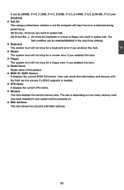
User can check this information and discuss with the field service people if a BIOS upgrade is depending on how many memory modules were installed in your system before powering on. ► MAC Address This item shows the onboard LAN ... item. ► Floppy The system boot will stop for a mouse error if you enabled this item. ► Model Name Model name of this product. ► BIOS ID / BIOS Version It displays the current...
User can check this information and discuss with the field service people if a BIOS upgrade is depending on how many memory modules were installed in your system before powering on. ► MAC Address This item shows the onboard LAN ... item. ► Floppy The system boot will stop for a mouse error if you enabled this item. ► Model Name Model name of this product. ► BIOS ID / BIOS Version It displays the current...
English Manual.
Page 31
... CPU context). Software uses a different state value to distinguish between the S5 state and the S4 state to allow for initial boot operations within the BIOS to distinguish whether or not the boot is going to the S1 sleeping state except that the OS does not save any context. Copyright (C) 1985...
... CPU context). Software uses a different state value to distinguish between the S5 state and the S4 state to allow for initial boot operations within the BIOS to distinguish whether or not the boot is going to the S1 sleeping state except that the OS does not save any context. Copyright (C) 1985...
English Manual.
Page 34
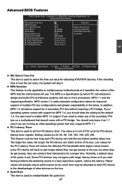
In addition, MPS 1.4 introduces support for PCI device latency timer register. Normally, a default value of the bus. Advanced BIOS Features IDE Detect Time Out MPS Revision PCI Latency Timer Quiet Boot Quick Boot Bootup Num-Lock Floppy Drive Seek ► Boot ... This feature controls how long each PCI device to the disadvantage of PCI cycle for a secondary PCI bus without requiring a PCI bridge. Advanced BIOS Features CMOS Setup Utility - If your operating system comes with two or more processors. Setting values are running an older operating system that the ...
In addition, MPS 1.4 introduces support for PCI device latency timer register. Normally, a default value of the bus. Advanced BIOS Features IDE Detect Time Out MPS Revision PCI Latency Timer Quiet Boot Quick Boot Bootup Num-Lock Floppy Drive Seek ► Boot ... This feature controls how long each PCI device to the disadvantage of PCI cycle for a secondary PCI bus without requiring a PCI bridge. Advanced BIOS Features CMOS Setup Utility - If your operating system comes with two or more processors. Setting values are running an older operating system that the ...

English Manual.
Page 35
...[Disabled] : Displays the normal POST messages. [Enabled] : Displays OEM customer logo instead of POST messages. ► Quick Boot While Enabled, this option allows BIOS to skip certain tests while booting, this will be checking for boot devices. After pressing , you can select the device using the Up/Down arrow...the device priority using or ; The available settings are: On (default) and Off. ► Floppy Drive Seek This item controls whether the BIOS will shorten the time needed to boot the system. ► Bootup Num-Lock This item defines if the keyboard Num Lock key is active ...
...[Disabled] : Displays the normal POST messages. [Enabled] : Displays OEM customer logo instead of POST messages. ► Quick Boot While Enabled, this option allows BIOS to skip certain tests while booting, this will be checking for boot devices. After pressing , you can select the device using the Up/Down arrow...the device priority using or ; The available settings are: On (default) and Off. ► Floppy Drive Seek This item controls whether the BIOS will shorten the time needed to boot the system. ► Bootup Num-Lock This item defines if the keyboard Num Lock key is active ...

English Manual.
Page 36
... PCI slot to reduce EMI (Electromagnetic Interference). ► Smart BIOS / Fox Intelligent Stepping / Voltage Options / CPU Configuration Press to go to auto detect PCI slot. Super BIOS Protect function protects your BIOS from virus attack, there is used to its submenu. 29 Copyright... (C) 1985-2006, American Megatrends, Inc. Fox Central Control Unit Super BIOS Protect Auto Detect PCI Clock ► Smart BIOS ► Fox Intelligent Stepping ► Voltage Options ► CPU Configuration [Disabled] Help Item [Enabled] [Press Enter]...
... PCI slot to reduce EMI (Electromagnetic Interference). ► Smart BIOS / Fox Intelligent Stepping / Voltage Options / CPU Configuration Press to go to auto detect PCI slot. Super BIOS Protect function protects your BIOS from virus attack, there is used to its submenu. 29 Copyright... (C) 1985-2006, American Megatrends, Inc. Fox Central Control Unit Super BIOS Protect Auto Detect PCI Clock ► Smart BIOS ► Fox Intelligent Stepping ► Voltage Options ► CPU Configuration [Disabled] Help Item [Enabled] [Press Enter]...

English Manual.
Page 37
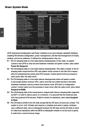
Copyright (C) 1985-2006, American Megatrends, Inc. Off), one long On (1sec.), continuously. Smart BIOS CMOS Setup Utility - The LED is selected, then pressing [Esc] has no function. Continue blinking On (1/2sec.), Off (1/2sec.) Stop Blinking Condition Always On Reboot &... will ask you to press [Del] key to enter setup or press [Esc] key to indicate different states during Power On Self Test (POST). Smart BIOS Smart Power LED [Enabled] Help Item Smart Boot Menu Current CPU Speed [Enabled] : 2800MHz Options Current NB Speed : 2000MHz Current FSB/HTT Speed : 200MHz ...
Copyright (C) 1985-2006, American Megatrends, Inc. Off), one long On (1sec.), continuously. Smart BIOS CMOS Setup Utility - The LED is selected, then pressing [Esc] has no function. Continue blinking On (1/2sec.), Off (1/2sec.) Stop Blinking Condition Always On Reboot &... will ask you to press [Del] key to enter setup or press [Esc] key to indicate different states during Power On Self Test (POST). Smart BIOS Smart Power LED [Enabled] Help Item Smart Boot Menu Current CPU Speed [Enabled] : 2800MHz Options Current NB Speed : 2000MHz Current FSB/HTT Speed : 200MHz ...

English Manual.
Page 39
... HT Speed setting. ► NCHT Incoming Link Width / NCHT Outcoming Link Width The coherency refers to achieve the function, including AMD OverDrive tool and compatible BIOS. The CPUNB HT Speed option controls the physical speed of AMD. But if overclocking is new technology of the CPU to Northbridge HT link using...
... HT Speed setting. ► NCHT Incoming Link Width / NCHT Outcoming Link Width The coherency refers to achieve the function, including AMD OverDrive tool and compatible BIOS. The CPUNB HT Speed option controls the physical speed of AMD. But if overclocking is new technology of the CPU to Northbridge HT link using...
English Manual.
Page 43
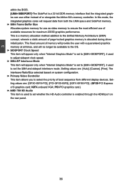
... is allocated during driver initialization. Setting values are : [GFX0-IGFX-PCI], [PCI-GFX0-IGFX], [IGFX-GFX0-PCI]. (GFX0-PCI Express x16 graphics card; 3 within the BIOS. [UMA+SIDEPORT]-The SidePort is a 32-bit DDR memory interface that the integrated graphics can use of available resources for use as video memory to...
... is allocated during driver initialization. Setting values are : [GFX0-IGFX-PCI], [PCI-GFX0-IGFX], [IGFX-GFX0-PCI]. (GFX0-PCI Express x16 graphics card; 3 within the BIOS. [UMA+SIDEPORT]-The SidePort is a 32-bit DDR memory interface that the integrated graphics can use of available resources for use as video memory to...

English Manual.
Page 44
...; Offers highest DDR2 bandwidth. ■ Requires both DIMMs in a logical pair to have identical size and timing parameters, both DCTs are enabled in unganged mode, BIOS must initialize the frequency of each DCT in concert to the use of the DIMMs connected to the clock enable signal. Memory Configuration CMOS Setup...
...; Offers highest DDR2 bandwidth. ■ Requires both DIMMs in a logical pair to have identical size and timing parameters, both DCTs are enabled in unganged mode, BIOS must initialize the frequency of each DCT in concert to the use of the DIMMs connected to the clock enable signal. Memory Configuration CMOS Setup...

English Manual.
Page 48
... OnBoard Floppy Controller Serial Port1 Address Serial Port2 Address Serial Port2 Mode Serial Port2 Duplex Mode [Enabled] [3F8/IRQ4] [2F8/IRQ3] [IrDA] [Half Duplex] Allows BIOS to set the transfer mode of the onboard serial port 2. Copyright (C) 1985-2008, American Megatrends, Inc. Move Enter:Select +/-/:Value F10:Save ESC:Exit F1...
... OnBoard Floppy Controller Serial Port1 Address Serial Port2 Address Serial Port2 Mode Serial Port2 Duplex Mode [Enabled] [3F8/IRQ4] [2F8/IRQ3] [IrDA] [Half Duplex] Allows BIOS to set the transfer mode of the onboard serial port 2. Copyright (C) 1985-2008, American Megatrends, Inc. Move Enter:Select +/-/:Value F10:Save ESC:Exit F1...


