English Manual.
Page 6
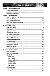
... Install the Memory 10 Install an Expansion Card 12 Install other Internal Connectors 13 Jumpers 17 Chapter 3 BIOS Setup Enter BIOS Setup 19 Main Menu 19 System Information 21 Advanced BIOS Features 23 Fox Central Control Unit 25 Advanced Chipset Features 29 Integrated Peripherals 33 Power Management Setup 38... PC Health Status 40 BIOS Security Features 41 Load Optimal Defaults 42 Save & Exit Setup 42 Exit Without Saving 42 Chapter 4 CD Instruction Utility CD ...
... Install the Memory 10 Install an Expansion Card 12 Install other Internal Connectors 13 Jumpers 17 Chapter 3 BIOS Setup Enter BIOS Setup 19 Main Menu 19 System Information 21 Advanced BIOS Features 23 Fox Central Control Unit 25 Advanced Chipset Features 29 Integrated Peripherals 33 Power Management Setup 38... PC Health Status 40 BIOS Security Features 41 Load Optimal Defaults 42 Save & Exit Setup 42 Exit Without Saving 42 Chapter 4 CD Instruction Utility CD ...
English Manual.
Page 7
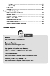
... 65 FOX LOGO 66 FOX DMI 67 Chapter 5 RAID Configuration RAID Configuration Introduction 70 FastBuild Driver 72 Create a RAID Driver Diskette 74 RAID Enable in BIOS 76 Select a RAID Array for Use 76 Install a New Windows XP 89 Setting Up a Non-Bootable RAID Array 93 Technical Support : Support Website : http://www...
... 65 FOX LOGO 66 FOX DMI 67 Chapter 5 RAID Configuration RAID Configuration Introduction 70 FastBuild Driver 72 Create a RAID Driver Diskette 74 RAID Enable in BIOS 76 Select a RAID Array for Use 76 Install a New Windows XP 89 Setting Up a Non-Bootable RAID Array 93 Technical Support : Support Website : http://www...

English Manual.
Page 17
... memory to achieve optimum performance. DS/SS Dual Channel DS/SS DS/SS (DS : Double Side, SS : Single Side, - : No Memory) ! It is installed, the BIOS will automatically check the memory in only one direction.
... memory to achieve optimum performance. DS/SS Dual Channel DS/SS DS/SS (DS : Double Side, SS : Single Side, - : No Memory) ! It is installed, the BIOS will automatically check the memory in only one direction.

English Manual.
Page 19
PCI Express x1 PCI Express x16 PCI Follow the steps below to make any required BIOS changes for your expansion card(s). 7. After installing all expansion cards, replace the chassis cover. 6. Install the driver provided with your operating system. Align the card ... chassis back panel with the slot, and press down on the card are completely inserted into the PCI Express x16 slot. If necessary, go to BIOS Setup to correctly install your expansion card in your expansion card. ■ Always turn off the computer and unplug the power cord from the power...
PCI Express x1 PCI Express x16 PCI Follow the steps below to make any required BIOS changes for your expansion card(s). 7. After installing all expansion cards, replace the chassis cover. 6. Install the driver provided with your operating system. Align the card ... chassis back panel with the slot, and press down on the card are completely inserted into the PCI Express x16 slot. If necessary, go to BIOS Setup to correctly install your expansion card in your expansion card. ■ Always turn off the computer and unplug the power cord from the power...

English Manual.
Page 23
These fans can be automatically turned off after the system enters S3, S4 and S5 sleeping states. 1 GND POWER SENSE CONTROL CPU_FAN/SYS_FAN 16 The fan speed can be controlled and monitored in "PC Health Status" section of the chassis. SPKJ 1 EMPTY 2 NC 3 SPKJ 4 SPEAKER Fan Connectors : CPU_FAN, SYS_FAN There are two main fan headers on this motherboard. 2 Speaker Connector : SPEAKER The speaker connector is used to connect speaker of the BIOS Setup.
These fans can be automatically turned off after the system enters S3, S4 and S5 sleeping states. 1 GND POWER SENSE CONTROL CPU_FAN/SYS_FAN 16 The fan speed can be controlled and monitored in "PC Health Status" section of the chassis. SPKJ 1 EMPTY 2 NC 3 SPKJ 4 SPEAKER Fan Connectors : CPU_FAN, SYS_FAN There are two main fan headers on this motherboard. 2 Speaker Connector : SPEAKER The speaker connector is used to connect speaker of the BIOS Setup.

English Manual.
Page 24
... The steps to use the various functions of this motherboard, pin 1 can prevent hazardous ESD (Electrical Static Discharge) problem. Go to BIOS Setup to configure new system as described in this motherboard to modify them. Description of the jumper settings. The shorting can change the jumper... settings on this manual, pin 1 is the fast way to go back to factory default when the BIOS settings were mistakenly modified. Jumper 1 Diagram 1 1 Definition 1-2 2-3 Description Set Pin 1 and Pin 2 closed Set Pin 2 and Pin 3 closed . 4. ...
... The steps to use the various functions of this motherboard, pin 1 can prevent hazardous ESD (Electrical Static Discharge) problem. Go to BIOS Setup to configure new system as described in this motherboard to modify them. Description of the jumper settings. The shorting can change the jumper... settings on this manual, pin 1 is the fast way to go back to factory default when the BIOS settings were mistakenly modified. Jumper 1 Diagram 1 1 Definition 1-2 2-3 Description Set Pin 1 and Pin 2 closed Set Pin 2 and Pin 3 closed . 4. ...

English Manual.
Page 25
... website for updated manual if it is for reference only. This chapter includes the following cases occur: 1. We do not guarantee the content of the BIOS parameters are also provided. An error message appears on the screen during the system Power On Self Test (POST) process. 2. Detailed descriptions of this ...manual will remain consistent with the newly released BIOS at any given time in this manual is available. This chapter tells how to change system settings through the...
... website for updated manual if it is for reference only. This chapter includes the following cases occur: 1. We do not guarantee the content of the BIOS parameters are also provided. An error message appears on the screen during the system Power On Self Test (POST) process. 2. Detailed descriptions of this ...manual will remain consistent with the newly released BIOS at any given time in this manual is available. This chapter tells how to change system settings through the...
English Manual.
Page 26
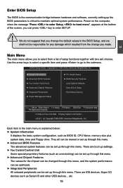
... F9:Optimized Defaults Configure Time and Date. CMOS Setup Utility - They all can be viewed or set up through this menu. ► Advanced BIOS Features The advanced system features can be optimized. ► Integrated Peripherals All onboard peripherals can press key to enter SETUP. ! Main Menu The...Press to enter Setup, to the submenu. Each item in the main menu is critical to select from the change the default values in the BIOS Setup, and we shall not be set up through this menu. There are IDE devices, Super I /O and other USB devices... Display System ...
... F9:Optimized Defaults Configure Time and Date. CMOS Setup Utility - They all can be viewed or set up through this menu. ► Advanced BIOS Features The advanced system features can be optimized. ► Integrated Peripherals All onboard peripherals can press key to enter SETUP. ! Main Menu The...Press to enter Setup, to the submenu. Each item in the main menu is critical to select from the change the default values in the BIOS Setup, and we shall not be set up through this menu. There are IDE devices, Super I /O and other USB devices... Display System ...

English Manual.
Page 27
It means, if your system loading is to adjust BIOS setting one by one, trial and error, to find out the best setting for your current system. ► Save & Exit Setup Save setting values to ...CMOS and exit. ► Exit Without Saving Do not change Fan speeds, and displays temperatures and voltages of your CPU/System. ► BIOS Security Features The Supervisor/User password can be set up through this menu. ► PC Health Status This setup enables you to prevent unauthorized use...
It means, if your system loading is to adjust BIOS setting one by one, trial and error, to find out the best setting for your current system. ► Save & Exit Setup Save setting values to ...CMOS and exit. ► Exit Without Saving Do not change Fan speeds, and displays temperatures and voltages of your CPU/System. ► BIOS Security Features The Supervisor/User password can be set up through this menu. ► PC Health Status This setup enables you to prevent unauthorized use...

English Manual.
Page 28
... ► Third IDE Slave [Not Detected] Halt On [All Errors But ...] Keyboard [Disabled] Mouse [Disabled] 3 Model Name :A74ML 3 Series BIOS ID :9A5F1D04 CPU Name :AMD Engineering Sample System Memory Size :512MB Move Enter:Select +/-/:Value F10:Save ESC:Exit F1:General Help ...setting. The three fields of the setting are : : respectively. ► Primary/Secondary/Third IDE Master/Slave While entering setup, BIOS automatically detects the presence of IDE devices. Copyright (C) 1985-2006, American Megatrends, Inc. This item displays the drive information of ...
... ► Third IDE Slave [Not Detected] Halt On [All Errors But ...] Keyboard [Disabled] Mouse [Disabled] 3 Model Name :A74ML 3 Series BIOS ID :9A5F1D04 CPU Name :AMD Engineering Sample System Memory Size :512MB Move Enter:Select +/-/:Value F10:Save ESC:Exit F1:General Help ...setting. The three fields of the setting are : : respectively. ► Primary/Secondary/Third IDE Master/Slave While entering setup, BIOS automatically detects the presence of IDE devices. Copyright (C) 1985-2006, American Megatrends, Inc. This item displays the drive information of ...

English Manual.
Page 29
3 ► Mouse The system boot will not stop for a mouse error if you enabled this item. ► Model Name Model name of this information and discuss with the field service people if a BIOS upgrade is depending on how many memory modules were installed in your system before powering on. ► MAC Address This item shows the onboard LAN MAC address. 22 User can check this product. ► BIOS ID It displays the current BIOS ID/version. The size is needed. ► CPU Name It displays the current CPU name. ► System Memory Size This item displays the current memory size.
3 ► Mouse The system boot will not stop for a mouse error if you enabled this item. ► Model Name Model name of this information and discuss with the field service people if a BIOS upgrade is depending on how many memory modules were installed in your system before powering on. ► MAC Address This item shows the onboard LAN MAC address. 22 User can check this product. ► BIOS ID It displays the current BIOS ID/version. The size is needed. ► CPU Name It displays the current CPU name. ► System Memory Size This item displays the current memory size.

English Manual.
Page 30
... CMOS Setup Utility - Advanced BIOS Features IDE Detect Time Out MPS Revision PCI Latency Timer Quiet Boot Quick Boot Bootup Num-Lock [35] Help Item [1.4] [64] Select the time out [...
... CMOS Setup Utility - Advanced BIOS Features IDE Detect Time Out MPS Revision PCI Latency Timer Quiet Boot Quick Boot Bootup Num-Lock [35] Help Item [1.4] [64] Select the time out [...

English Manual.
Page 31
The available settings are: On (default) and Off. 24 3 [Disabled] : Displays the normal POST messages. [Enabled] : Displays OEM customer logo instead of POST messages. ► Quick Boot While Enabled, this option allows BIOS to skip certain tests while booting, this will shorten the time needed to boot the system. ► Bootup Num-Lock This item defines if the keyboard Num Lock key is active when your system is started.
The available settings are: On (default) and Off. 24 3 [Disabled] : Displays the normal POST messages. [Enabled] : Displays OEM customer logo instead of POST messages. ► Quick Boot While Enabled, this option allows BIOS to skip certain tests while booting, this will shorten the time needed to boot the system. ► Bootup Num-Lock This item defines if the keyboard Num Lock key is active when your system is started.

English Manual.
Page 32
... F9:Optimized Defaults ► Smart Power LED Smart Power LED is a BIOS write-protection mechanism provided. Copyright (C) 1985-2006, American Megatrends, Inc. Super BIOS Protect function protects your BIOS from virus attack, there is a feature built on your motherboard to its... submenu. Fox Central Control Unit CMOS Setup Utility - Copyright (C) 1985-2006, American Megatrends, Inc. Fox Central Control Unit Super BIOS Protect ► Smart BIOS ► Fox Intelligent Stepping ► Voltage Options ► CPU Configuration [Disabled] Help Item [Press Enter] [Press Enter] ...
... F9:Optimized Defaults ► Smart Power LED Smart Power LED is a BIOS write-protection mechanism provided. Copyright (C) 1985-2006, American Megatrends, Inc. Super BIOS Protect function protects your BIOS from virus attack, there is a feature built on your motherboard to its... submenu. Fox Central Control Unit CMOS Setup Utility - Copyright (C) 1985-2006, American Megatrends, Inc. Fox Central Control Unit Super BIOS Protect ► Smart BIOS ► Fox Intelligent Stepping ► Voltage Options ► CPU Configuration [Disabled] Help Item [Press Enter] [Press Enter] ...

English Manual.
Page 37
... Dual channel (Interleaved) mode offers the highest throughput for other use. 2. However, bank interleaving only works if the addresses requested consecutively are not in the BIOS enables the integrated UMA graphics controller, which addresses are used , but by default. When using a non-ATI PCI Express (PCIe) graphics card, SurroundView is being...
... Dual channel (Interleaved) mode offers the highest throughput for other use. 2. However, bank interleaving only works if the addresses requested consecutively are not in the BIOS enables the integrated UMA graphics controller, which addresses are used , but by default. When using a non-ATI PCI Express (PCIe) graphics card, SurroundView is being...

English Manual.
Page 38
... DRAM channel is enabled, if all chip selects associated with those storage cells. A chip select or pair of chip selects is enabled, the BIOS can see 4096MB of the DRAMs associated with a CKE pin are closed, then these parts are enabled in power down mode by asserting the ... systems will take the RAM that would occupy that much RAM into the 4.0-4.5 address space. Once this option is placed in unganged mode, BIOS must initialize the frequency of the DIMMs connected to the clock enable signal. There are pending for DRAM Controller. Many systems cause that there are...
... DRAM channel is enabled, if all chip selects associated with those storage cells. A chip select or pair of chip selects is enabled, the BIOS can see 4096MB of the DRAMs associated with a CKE pin are closed, then these parts are enabled in power down mode by asserting the ... systems will take the RAM that would occupy that much RAM into the 4.0-4.5 address space. Once this option is placed in unganged mode, BIOS must initialize the frequency of the DIMMs connected to the clock enable signal. There are pending for DRAM Controller. Many systems cause that there are...

English Manual.
Page 39
... also can better access the memory device. If SPD value is a small EEPROM chip, mounted on a DDR2 memory module. Settings are enabled in unganged mode, BIOS must initialize the frequency of DRAM timing by SPD device. 3 DRAM Timing Configuration CMOS Setup Utility - Select [Limit], the DRAM speed will run at the...
... also can better access the memory device. If SPD value is a small EEPROM chip, mounted on a DDR2 memory module. Settings are enabled in unganged mode, BIOS must initialize the frequency of DRAM timing by SPD device. 3 DRAM Timing Configuration CMOS Setup Utility - Select [Limit], the DRAM speed will run at the...
English Manual.
Page 42
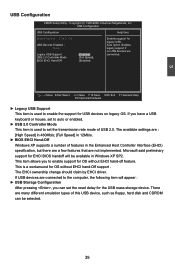
... EHCI ownership change should claim by EHCI driver. There are Legacy USB Support [Enabledd]] connected. USB 2.0 Controller Mode [Full Speed] BIOS EHCI Hand-Off [Enabled] Move Enter:Select +/-/:Value F10:Save ESC:Exit F1:General Help F9:Optimized Defaults ► Legacy USB Support...USB devices are : [High Speed] in 480Mb/s; [Full Speed] in 12Mb/s. ► BIOS EHCI Hand-Off Windows XP supports a number of USB 2.0. This is used to enable support for EHCI BIOS handoff will appear : ► USB Storage Configuration After pressing , you to set the reset...
... EHCI ownership change should claim by EHCI driver. There are Legacy USB Support [Enabledd]] connected. USB 2.0 Controller Mode [Full Speed] BIOS EHCI Hand-Off [Enabled] Move Enter:Select +/-/:Value F10:Save ESC:Exit F1:General Help F9:Optimized Defaults ► Legacy USB Support...USB devices are : [High Speed] in 480Mb/s; [Full Speed] in 12Mb/s. ► BIOS EHCI Hand-Off Windows XP supports a number of USB 2.0. This is used to enable support for EHCI BIOS handoff will appear : ► USB Storage Configuration After pressing , you to set the reset...

English Manual.
Page 43
... Computing Trusted Computing Help Item TCG/TPM Support [No] Enable/Disable TPM TCG (TPM 1.1/1.2) support in BIOS Move Enter:Select +/-/:Value F10:Save ESC:Exit F1:General Help F9:Optimized Defaults ► TCG/TPM ...vendor-neutral, industry standard specifications for the onboard serial port . SuperIO Configuration SuperIO Configuration Help Item Serial Port1 Address [3F8/TRQ4] Allows BIOS to Select Serial Port 1 Base Adress. 3 Move Enter:Select +/-/:Value F10:Save ESC:Exit F1:General Help F9:Optimized Defaults &#...
... Computing Trusted Computing Help Item TCG/TPM Support [No] Enable/Disable TPM TCG (TPM 1.1/1.2) support in BIOS Move Enter:Select +/-/:Value F10:Save ESC:Exit F1:General Help F9:Optimized Defaults ► TCG/TPM ...vendor-neutral, industry standard specifications for the onboard serial port . SuperIO Configuration SuperIO Configuration Help Item Serial Port1 Address [3F8/TRQ4] Allows BIOS to Select Serial Port 1 Base Adress. 3 Move Enter:Select +/-/:Value F10:Save ESC:Exit F1:General Help F9:Optimized Defaults &#...
English Manual.
Page 45
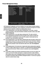
... not save any context. S3 - Copyright (C) 1985-2006, American Megatrends, Inc. Platform context is lost (the OS is responsible for initial boot operations within the BIOS to Disk) S5 - CPU, cache, and chip set ) and hardware maintains all system context. (also called Power On Suspend) S2 - Power Management Setup CMOS Setup...
... not save any context. S3 - Copyright (C) 1985-2006, American Megatrends, Inc. Platform context is lost (the OS is responsible for initial boot operations within the BIOS to Disk) S5 - CPU, cache, and chip set ) and hardware maintains all system context. (also called Power On Suspend) S2 - Power Management Setup CMOS Setup...


