User Manual
Page 3
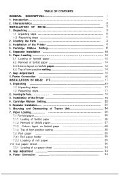
... setting 28 7.2 Roll paper 29 7.2.1 Roll paper holder 29 7.2.2 Loading of roll paper 29 7.3 Cut paper sheet 30 7.3.1 Loading of the Printer 19 4. Power Connection 16 INSTALLATION OF MX-82 F/T 17 1. Cartridge Ribbon Setting 22 5. Mounting and Dismounting of form position setting 14 7. Power Connection 34 Counting the Parts 3 3. Cartridge Ribbon Setting 8 5. Installation of cut paper sheet 30 8. Paper Loading 25 7.1 Fanfold paper 25 7.1.1 Loading of fanfold paper 25 7.1.2 Removal of fanfold paper 27 7.1.3 Column layout on fanfold paper 14 6.4 Top of Tractor Unit...
... setting 28 7.2 Roll paper 29 7.2.1 Roll paper holder 29 7.2.2 Loading of roll paper 29 7.3 Cut paper sheet 30 7.3.1 Loading of the Printer 19 4. Power Connection 16 INSTALLATION OF MX-82 F/T 17 1. Cartridge Ribbon Setting 22 5. Mounting and Dismounting of form position setting 14 7. Power Connection 34 Counting the Parts 3 3. Cartridge Ribbon Setting 8 5. Installation of cut paper sheet 30 8. Paper Loading 25 7.1 Fanfold paper 25 7.1.1 Loading of fanfold paper 25 7.1.2 Removal of fanfold paper 27 7.1.3 Column layout on fanfold paper 14 6.4 Top of Tractor Unit...
User Manual
Page 4
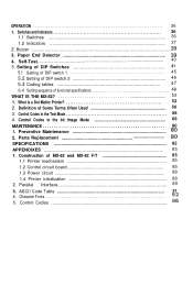
... Used 56 3. Control Codes in the bit Image Mode 69 MAINTENANCE 80 1. Control Codes in the Text Mode 58 4. Preventive Maintenance i3 2. Parallel Interface 89 3. Switches and Indicators 36 1.1 Switches 36 1.2 Indicators 37 2. What is a Dot Matrix Printer 53 2. Definition of funcional specifications 48 WHAT IS THE MX-82 53 1. Construction of MX-82 and MX-82 F/T 85 1.1 Printer mechanism 85 1.2 Control circuit board 85 1.3 Power circuit 88 1.4 Printer initialization 88 2. Control Codes Paper End Detector 4. ASCII Code...
... Used 56 3. Control Codes in the bit Image Mode 69 MAINTENANCE 80 1. Control Codes in the Text Mode 58 4. Preventive Maintenance i3 2. Parallel Interface 89 3. Switches and Indicators 36 1.1 Switches 36 1.2 Indicators 37 2. What is a Dot Matrix Printer 53 2. Definition of funcional specifications 48 WHAT IS THE MX-82 53 1. Construction of MX-82 and MX-82 F/T 85 1.1 Printer mechanism 85 1.2 Control circuit board 85 1.3 Power circuit 88 1.4 Printer initialization 88 2. Control Codes Paper End Detector 4. ASCII Code...
User Manual
Page 5
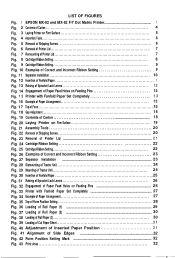
LIST OF FIGURES Fig. 1 EPSON MX-82 and MX-82 F/T Dot Matrix Printer 1 Fig. 2 Contents of Carton 4 Fig. 3 Laying Printer on Firm Surface 5 Fig. 4 Assembly Tools 6 Fig. 5 Removal of Shipping Screws 6 Fig. 6 Removal of Printer Lid 7 Fig. 7 Remounting of Printer Lid 7 Fig. 8 Cartridge Ribbon Setting 8 Fig. 9 Cartridge Ribbon Setting 9 Fig. 10 Examples of Correct and Incorrect Ribbon Setting 9 Fig. 11 Separator Installation 10 Fig. 12 Insertion of Fanfold Paper 11...
LIST OF FIGURES Fig. 1 EPSON MX-82 and MX-82 F/T Dot Matrix Printer 1 Fig. 2 Contents of Carton 4 Fig. 3 Laying Printer on Firm Surface 5 Fig. 4 Assembly Tools 6 Fig. 5 Removal of Shipping Screws 6 Fig. 6 Removal of Printer Lid 7 Fig. 7 Remounting of Printer Lid 7 Fig. 8 Cartridge Ribbon Setting 8 Fig. 9 Cartridge Ribbon Setting 9 Fig. 10 Examples of Correct and Incorrect Ribbon Setting 9 Fig. 11 Separator Installation 10 Fig. 12 Insertion of Fanfold Paper 11...
User Manual
Page 6
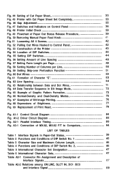
... Paper Sheet Set Completely 33 Fig. 46 Gap Adjustment 35 Fig. 47 Switches and Indicators on Control Panel 36 Fig. 48 Printer Initial Check 38 Fig. 49 Flowchart of Paper Out Status Release Procedure 39 Fig. 50 Removing Manual Paper Feed Knob 41 Fig. 51 Loosening All 4 Screws 42 Fig. 52 Pulling Out Wires Hooked to Computers 94 LIST OF TABLES Table 1 Interface Signals in Bit Image Mode...
... Paper Sheet Set Completely 33 Fig. 46 Gap Adjustment 35 Fig. 47 Switches and Indicators on Control Panel 36 Fig. 48 Printer Initial Check 38 Fig. 49 Flowchart of Paper Out Status Release Procedure 39 Fig. 50 Removing Manual Paper Feed Knob 41 Fig. 51 Loosening All 4 Screws 42 Fig. 52 Pulling Out Wires Hooked to Computers 94 LIST OF TABLES Table 1 Interface Signals in Bit Image Mode...
User Manual
Page 7
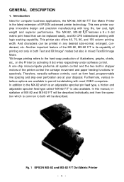
.... Therefore, versatile software controls, such as form feed, programmable line spacing and skip-over perforation are available to the hard-copy production of MX-82 and MX-82 F/T will be described individually and then the operation which is an adjustable sprocket pin feed type, a friction and adjustable sprocket feed type called "MX-82 F/T" is common to both Text and Bit Image" modes but also in mixed Text/Bit Image Mode. *Bit Image printing refers to...
.... Therefore, versatile software controls, such as form feed, programmable line spacing and skip-over perforation are available to the hard-copy production of MX-82 and MX-82 F/T will be described individually and then the operation which is an adjustable sprocket pin feed type, a friction and adjustable sprocket feed type called "MX-82 F/T" is common to both Text and Bit Image" modes but also in mixed Text/Bit Image Mode. *Bit Image printing refers to...
User Manual
Page 8
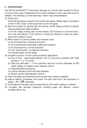
.... (7) 8 international character sets are selectable by bidirectional printing with standard equipment including paper end detector, custom cartridge ribbon, etc. -2- In the Bit Image printing, both normal density (576 dots/line in horizontal direction) and dual density (1152 dots/line in propotion to the vertical dot space. Similar figure in horizontal direction) modes are freely available. Characteristics The MX-82 and MX-82 F/T have been designed...
.... (7) 8 international character sets are selectable by bidirectional printing with standard equipment including paper end detector, custom cartridge ribbon, etc. -2- In the Bit Image printing, both normal density (576 dots/line in horizontal direction) and dual density (1152 dots/line in propotion to the vertical dot space. Similar figure in horizontal direction) modes are freely available. Characteristics The MX-82 and MX-82 F/T have been designed...
User Manual
Page 11
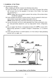
... of the Printer. NOTE: Rubber feet are provided to prevent the marring of the surface where the MX-82 is placed. (b) Avoid operating the MX-82 in the back of the print head. (c) Connect the power cord to an outlet separated from those connected to electric noise-generating equipment, such as heater, etc. ,i , CRT displav iFloppy disk unit MX-82 / I 2i!!J Interface cable / I Paper / III II...
... of the Printer. NOTE: Rubber feet are provided to prevent the marring of the surface where the MX-82 is placed. (b) Avoid operating the MX-82 in the back of the print head. (c) Connect the power cord to an outlet separated from those connected to electric noise-generating equipment, such as heater, etc. ,i , CRT displav iFloppy disk unit MX-82 / I 2i!!J Interface cable / I Paper / III II...
User Manual
Page 16
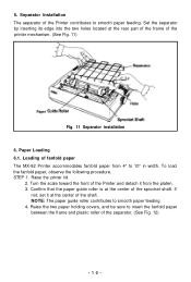
... MX-82 Printer accommodates fanfold paper from the platen. 3. Raise the two paper holding covers, and be sure to smooth paper feeding. 4. Confirm that the paper guide roller is at the rear part of the frame of the Printer contributes to 10" in width. Paper Loading 6.1. If not, set it from 4" to smooth paper feeding. 5. Separator Installation The separator of the printer mechanism. (See Fig. 11) Paper Fig. 11 Separator installation 6. To load...
... MX-82 Printer accommodates fanfold paper from the platen. 3. Raise the two paper holding covers, and be sure to smooth paper feeding. 4. Confirm that the paper guide roller is at the rear part of the frame of the Printer contributes to 10" in width. Paper Loading 6.1. If not, set it from 4" to smooth paper feeding. 5. Separator Installation The separator of the printer mechanism. (See Fig. 11) Paper Fig. 11 Separator installation 6. To load...
User Manual
Page 20
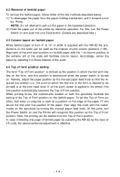
... not attempt to 10" in the backward direction. (2) Feed the paper out of the printer by adjusting it forward out of fanfold paper by operating the MX-82 by turning the manual paper feed knob. Alignment of the print start position on fanfold paper with the MX-82 the graduations on the fanfold paper. In case of feeding one page of the Printer. Now, the printing can be started from 4" to pull out...
... not attempt to 10" in the backward direction. (2) Feed the paper out of the printer by adjusting it forward out of fanfold paper by operating the MX-82 by turning the manual paper feed knob. Alignment of the print start position on fanfold paper with the MX-82 the graduations on the fanfold paper. In case of feeding one page of the Printer. Now, the printing can be started from 4" to pull out...
User Manual
Page 22
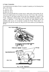
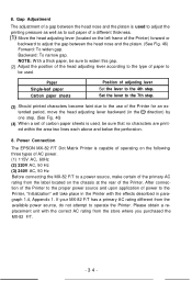
... operating on the following three types of AC power. (1) 115V AC, 60 Hz (2) 220V AC, 50 Hz (3) 240V AC, 50 Hz Before connecting the MX-82 to a power source, make certain of the primary AC rating from the label located on the chassis at the rear of power to operate the Printer. Head Adjusting Leve (Side View) \@ F--- -w ) 7th step Fig. 18 Gap Adjustment -16- Please obtain a replacement unit...
... operating on the following three types of AC power. (1) 115V AC, 60 Hz (2) 220V AC, 50 Hz (3) 240V AC, 50 Hz Before connecting the MX-82 to a power source, make certain of the primary AC rating from the label located on the chassis at the rear of power to operate the Printer. Head Adjusting Leve (Side View) \@ F--- -w ) 7th step Fig. 18 Gap Adjustment -16- Please obtain a replacement unit...
User Manual
Page 36
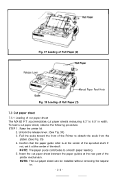
... be installed without removing the separa- NOTE: The cut paper sheet, observe the following procedure. Insert the cut paper sheet between the paper guides at the rear part of cut paper sheet The MX-82 F/T accommodates cut paper sheets measuring 8.3" to 8.5" in width. Unlock the release lever. (See Fig. 39) 3. Raise the printer lid. 2. r Fig. 37 Loading of Roll Paper (2) Release Lever Manual Paper Feed Knob Fig. 38 Loading of Roll Paper (3) 7.3 Cut paper sheet 7.3.1 Loading...
... be installed without removing the separa- NOTE: The cut paper sheet, observe the following procedure. Insert the cut paper sheet between the paper guides at the rear part of cut paper sheet The MX-82 F/T accommodates cut paper sheets measuring 8.3" to 8.5" in width. Unlock the release lever. (See Fig. 39) 3. Raise the printer lid. 2. r Fig. 37 Loading of Roll Paper (2) Release Lever Manual Paper Feed Knob Fig. 38 Loading of Roll Paper (3) 7.3 Cut paper sheet 7.3.1 Loading...
User Manual
Page 40
... Before connecting the MX-82 F/T to the 4th step. If your MX-82 F/T has a primary AC rating different from the label located on the left frame of adjusting lever Set the lever to a power source, make certain of the Printer. Set the lever to the 7th step. (3) Should printed characters become faint due to the use of the Printer for an extended period, move the head adjusting...
... Before connecting the MX-82 F/T to the 4th step. If your MX-82 F/T has a primary AC rating different from the label located on the left frame of adjusting lever Set the lever to a power source, make certain of the Printer. Set the lever to the 7th step. (3) Should printed characters become faint due to the use of the Printer for an extended period, move the head adjusting...
User Manual
Page 42
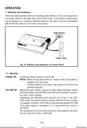
... paper is turned on the right side of the Printer case. The operations of the paper may prevent the Printer from operating properly. In this switch on, check to the Printer. Incorrect setting of the Line Feed and Form Feed switches are three switches and four indicators (green LED's) on the control panel and one power switch on after paper has been loaded, the Printer enters the ON-LINE mode and can be utilized in the Printer. Switches...
... paper is turned on the right side of the Printer case. The operations of the paper may prevent the Printer from operating properly. In this switch on, check to the Printer. Incorrect setting of the Line Feed and Form Feed switches are three switches and four indicators (green LED's) on the control panel and one power switch on after paper has been loaded, the Printer enters the ON-LINE mode and can be utilized in the Printer. Switches...
User Manual
Page 47
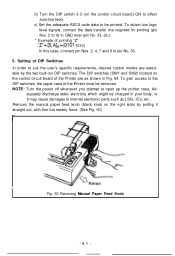
... DIP Switches In order to suit the user's specific requirements, desired control modes are as shown in your body, or it straight out, with firm but steady force. (See Fig. 50) Fig. 50 Removing Manual Paper Feed Knob -41- Setting of the Printer are selectable by pulling it may cause damages to effect auto-line feed. NOTE: Turn the power off whenever you attempt to GND level...
... DIP Switches In order to suit the user's specific requirements, desired control modes are as shown in your body, or it straight out, with firm but steady force. (See Fig. 50) Fig. 50 Removing Manual Paper Feed Knob -41- Setting of the Printer are selectable by pulling it may cause damages to effect auto-line feed. NOTE: Turn the power off whenever you attempt to GND level...

User Manual
Page 58
... MX-82, MX-82 F/T (hereinafter refered to as "Bit Image". 1. The contents of hardware and software. But we define its print mode as MX-82) from the viewpoint of the chapter are marketed in the bit image mode 5. One is the text mode, another is a dot matrix printer? 2. The serial printer means that it cannot print data at almost the same time. The receive only printer means that it cannot send data...
... MX-82, MX-82 F/T (hereinafter refered to as "Bit Image". 1. The contents of hardware and software. But we define its print mode as MX-82) from the viewpoint of the chapter are marketed in the bit image mode 5. One is the text mode, another is a dot matrix printer? 2. The serial printer means that it cannot print data at almost the same time. The receive only printer means that it cannot send data...
User Manual
Page 64
... the next predetermined Top of line spacing is governed by the DIP switch setting at that time. tion where the print head stops. The excess tab positions, if specified, will cause incorrect data printout. -58- The NUL code should be ignored. NOTES: 1. The Top of Form is determined when the POWER switch is turned on the control circuit board set in the ON position...
... the next predetermined Top of line spacing is governed by the DIP switch setting at that time. tion where the print head stops. The excess tab positions, if specified, will cause incorrect data printout. -58- The NUL code should be ignored. NOTES: 1. The Top of Form is determined when the POWER switch is turned on the control circuit board set in the ON position...
User Manual
Page 67
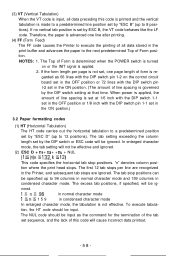
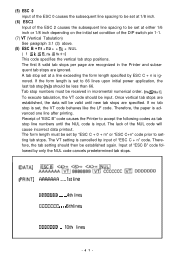
... DIP switch pin 1-1. (7) VT (Vertical Tabulation) See paragraph 3.1 (3) above. (8) ESC B + nc + n2 + + nk + NUL ( 1 5 k5 8,nks nk+l) This code specifies the vertical tab stop is set by "ESC C + 0 + m" or "ESC C+n" code prior to setting tab stops. The VT setting is cancelled by only the NUL code cancels predetermined tab stops. If no tab stop positions. Therefore, the paper is advanced one line after printing. DATA] PRINT...
... DIP switch pin 1-1. (7) VT (Vertical Tabulation) See paragraph 3.1 (3) above. (8) ESC B + nc + n2 + + nk + NUL ( 1 5 k5 8,nks nk+l) This code specifies the vertical tab stop is set by "ESC C + 0 + m" or "ESC C+n" code prior to setting tab stops. The VT setting is cancelled by only the NUL code cancels predetermined tab stops. If no tab stop positions. Therefore, the paper is advanced one line after printing. DATA] PRINT...
User Manual
Page 71
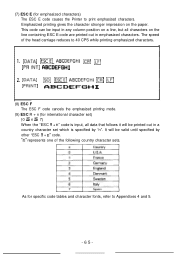
(7) ESC E (for specific code tables and character fonts, refer to Appendixes 4 and 5. -65- As for emphasized characters) The ESC E code causes the Printer to 40 CPS while printing emphasized characters. 1. [DATAI -E] ABCDEFGHI ICR] ILF] LPR INTI CIBCDEFGHI 2. [DATA] [PRINT] m (ESCE] ABCDEFGHI m m ABCDEFGH I (8) ESC F The ESC F code cancels the emphasized printing mode. (9) ESC R + n (for international character set) (0 S n 5 7) When the "ESC R + n" code is specified by...
(7) ESC E (for specific code tables and character fonts, refer to Appendixes 4 and 5. -65- As for emphasized characters) The ESC E code causes the Printer to 40 CPS while printing emphasized characters. 1. [DATAI -E] ABCDEFGHI ICR] ILF] LPR INTI CIBCDEFGHI 2. [DATA] [PRINT] m (ESCE] ABCDEFGHI m m ABCDEFGH I (8) ESC F The ESC F code cancels the emphasized printing mode. (9) ESC R + n (for international character set) (0 S n 5 7) When the "ESC R + n" code is specified by...
User Manual
Page 73
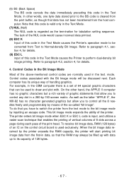
... L input of the print head. Refer to paragraph 4.2, section 4, for tabulation setting sequence. The printer enters bit image mode when ESC K or ESC L code is cleared from the print buffer, as though that this code in the Text Mode causes the Printer's operation mode to be filled up with data up to its unique way of the above-mentioned control codes are normally used exclusively. Control codes associated with . As...
... L input of the print head. Refer to paragraph 4.2, section 4, for tabulation setting sequence. The printer enters bit image mode when ESC K or ESC L code is cleared from the print buffer, as though that this code in the Text Mode causes the Printer's operation mode to be filled up with data up to its unique way of the above-mentioned control codes are normally used exclusively. Control codes associated with . As...
User Manual
Page 93
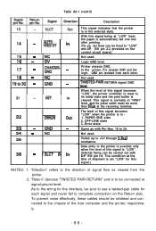
... this signal becomes "LOW", the printer controller is reset to its pulse width must be fixed to "LOW" with Pin Nos. 19 to complete connection on the control circuit board.) Not used. To prevent noise effectively, these cables should be connected at the receiving terminal. Printer chassis GND. Error state Same as viewed from each signal and never fail to 30. "Direction" refers to...
... this signal becomes "LOW", the printer controller is reset to its pulse width must be fixed to "LOW" with Pin Nos. 19 to complete connection on the control circuit board.) Not used. To prevent noise effectively, these cables should be connected at the receiving terminal. Printer chassis GND. Error state Same as viewed from each signal and never fail to 30. "Direction" refers to...


