User Guide
Page 1
... e-7050/610i supports up to 1066MHz FSB CPU's) ‰ Operating systems Supports Windows XP and Windows Vista. ‰ Contains an NVIDIA nForce MCP and integrated GeForce graphics ‰ System Memory • Single-channel DDR2 667/533 • Supports up to 4 GB DDR2 memory (2GB x 2) ‰ USB 2.0 Ports • Supports hot plug • Up to eight (4 onboard) USB 2.0 ports • Supports USB 2.0 protocol up to install and connect your new EVGA e-7050/610i GPU motherboard with integrated GeForce graphics processing...
... e-7050/610i supports up to 1066MHz FSB CPU's) ‰ Operating systems Supports Windows XP and Windows Vista. ‰ Contains an NVIDIA nForce MCP and integrated GeForce graphics ‰ System Memory • Single-channel DDR2 667/533 • Supports up to 4 GB DDR2 memory (2GB x 2) ‰ USB 2.0 Ports • Supports hot plug • Up to eight (4 onboard) USB 2.0 ports • Supports USB 2.0 protocol up to install and connect your new EVGA e-7050/610i GPU motherboard with integrated GeForce graphics processing...

User Guide
Page 2
... II connectors • Support for RAID 0, RAID 1 • Supports hot plug and NCQ (Native Command Queuing ) ‰ Onboard LAN • LAN interfaces built-in onboard • 10/100 LAN ‰ Onboard Audio • Supports 6-channel audio • Supports Jack-Sensing function ‰ PCI Express x16 Support • Supports 4 GB/sec (8 GB/sec concurrent) bandwidth ‰ Onboard Video • Integrated video • A VGA output is provided ‰ Expansion Slots • Two PCI slots • One PCI Express x1 slot • One PCI Express x16 Graphics slot
... II connectors • Support for RAID 0, RAID 1 • Supports hot plug and NCQ (Native Command Queuing ) ‰ Onboard LAN • LAN interfaces built-in onboard • 10/100 LAN ‰ Onboard Audio • Supports 6-channel audio • Supports Jack-Sensing function ‰ PCI Express x16 Support • Supports 4 GB/sec (8 GB/sec concurrent) bandwidth ‰ Onboard Video • Integrated video • A VGA output is provided ‰ Expansion Slots • Two PCI slots • One PCI Express x1 slot • One PCI Express x16 Graphics slot
User Guide
Page 3
... the back panel connectors. The topics covered in this section are: • Preparing the motherboard • Installing the CPU • Installing the CPU fan • Installing the memory • Installing the motherboard • Connecting cables and setting switches Safety Instructions To reduce the risk of the motherboard. Remember to remove power from your computer by disconnecting the AC main source before removing or installing any equipment from/to the computer chassis. Hardware Installation This section...
... the back panel connectors. The topics covered in this section are: • Preparing the motherboard • Installing the CPU • Installing the CPU fan • Installing the memory • Installing the motherboard • Connecting cables and setting switches Safety Instructions To reduce the risk of the motherboard. Remember to remove power from your computer by disconnecting the AC main source before removing or installing any equipment from/to the computer chassis. Hardware Installation This section...
User Guide
Page 4
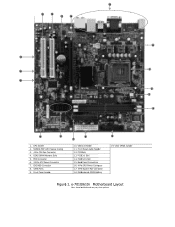
... Memory Slots 5. FDD Connector 6. 24-Pin ATX Power Connector 7. PCI-E x1 Slot 14. SATA Ports 9. PCI-E x16 Slot 15. Clear CMOS Jumper Figure 1. e-7010/610i Motherboard Layout Note: Actual motherboard may vary from pictures Motherboard CMOS Battery 5 19. USB 2.0 Header 11. 15 12 12 13 14 17 11 10 18 19 10 16 1 2 3 4 9 8 1. IDE HDD Connector 8. NVIDIA MCP with Passive Cooling 3. 4-Pin CPU Fan Connector 4. PCI Slots 13. CPU Socket 2. Front Panel Header 6 7 10. Front Panel Audio Header 12. Back Panel Connectors 16. 4-Pin CPU Power Connector 17. 3-Pin...
... Memory Slots 5. FDD Connector 6. 24-Pin ATX Power Connector 7. PCI-E x1 Slot 14. SATA Ports 9. PCI-E x16 Slot 15. Clear CMOS Jumper Figure 1. e-7010/610i Motherboard Layout Note: Actual motherboard may vary from pictures Motherboard CMOS Battery 5 19. USB 2.0 Header 11. 15 12 12 13 14 17 11 10 18 19 10 16 1 2 3 4 9 8 1. IDE HDD Connector 8. NVIDIA MCP with Passive Cooling 3. 4-Pin CPU Fan Connector 4. PCI Slots 13. CPU Socket 2. Front Panel Header 6 7 10. Front Panel Audio Header 12. Back Panel Connectors 16. 4-Pin CPU Power Connector 17. 3-Pin...
User Guide
Page 5
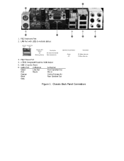
LAN Port with LEDs to indicate status: 5 5 6 Activity LED Status Off Blinking (Green) Description No data transmission Data transmission Speed/Link LED Status Green Off 3. PS/2 Mouse Port 4. e-7050 Integrated Graphics VGA Output 5. USB 2.0 ports (Four) 6. Audio Port Green Pink Orange Black Grey 2-Channel Line-Out Mic In 6-Channel Front Speaker Out Mic In Center/Subwoofer Rear Speaker Out Description 100 Mbps data rate 10 Mbps data rate Figure 1. Chassis Back Panel Connectors PS/2 Keyboard Port 2. 2 1 3 4 1.
LAN Port with LEDs to indicate status: 5 5 6 Activity LED Status Off Blinking (Green) Description No data transmission Data transmission Speed/Link LED Status Green Off 3. PS/2 Mouse Port 4. e-7050 Integrated Graphics VGA Output 5. USB 2.0 ports (Four) 6. Audio Port Green Pink Orange Black Grey 2-Channel Line-Out Mic In 6-Channel Front Speaker Out Mic In Center/Subwoofer Rear Speaker Out Description 100 Mbps data rate 10 Mbps data rate Figure 1. Chassis Back Panel Connectors PS/2 Keyboard Port 2. 2 1 3 4 1.
User Guide
Page 6
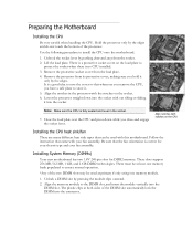
... the load plate. These slots support 256 MB, 512 MB, 1 GB, and 2 GB DDR2 technologies. Close the load plate over the CPU and press down and away from the load plate. 4. Installing System Memory (DIMMs) Your new motherboard has two 1.8V 240-pin slots for your chassis type and your fan assembly. Be sure that whenever you remove the CPU, you close and engage the socket lever. There...
... the load plate. These slots support 256 MB, 512 MB, 1 GB, and 2 GB DDR2 technologies. Close the load plate over the CPU and press down and away from the load plate. 4. Installing System Memory (DIMMs) Your new motherboard has two 1.8V 240-pin slots for your chassis type and your fan assembly. Be sure that whenever you remove the CPU, you close and engage the socket lever. There...
User Guide
Page 7
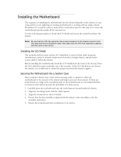
Also make sure the CPU Fan assembly is aligned with a mounting hole on the covers. If there are replacing an existing motherboard or working with a minimum of six screws. Secure the motherboard with an empty chassis. Installing the Motherboard The sequence of installing the motherboard into the chassis depends on the chassis you are using and if you are studs that do not align with...
Also make sure the CPU Fan assembly is aligned with a mounting hole on the covers. If there are replacing an existing motherboard or working with a minimum of six screws. Secure the motherboard with an empty chassis. Installing the Motherboard The sequence of installing the motherboard into the chassis depends on the chassis you are using and if you are studs that do not align with...
User Guide
Page 8
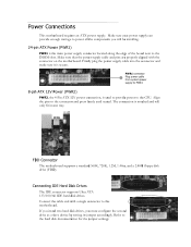
... the connector on the motherboard. Firmly plug the power supply cable into the connector and make sure it is used to provide power to power all the components you must configure the second drive as a slave device by setting its jumper accordingly. Connecting IDE Hard Disk Drives The IDE connector supports Ultra ATA 133/100/66 IDE hard disk drives. Power Connections This motherboard requires an ATX power supply. FDD Connector The motherboard supports a standard 360K, 720K, 1.2M, 1.44m, and a 2.88M floppy disk drive (FDD). If you install two hard disk drives, you...
... the connector on the motherboard. Firmly plug the power supply cable into the connector and make sure it is used to provide power to power all the components you must configure the second drive as a slave device by setting its jumper accordingly. Connecting IDE Hard Disk Drives The IDE connector supports Ultra ATA 133/100/66 IDE hard disk drives. Power Connections This motherboard requires an ATX power supply. FDD Connector The motherboard supports a standard 360K, 720K, 1.2M, 1.44m, and a 2.88M floppy disk drive (FDD). If you install two hard disk drives, you...
User Guide
Page 9
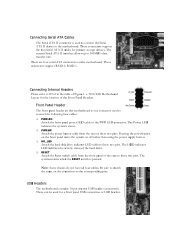
... when the RESET switch is one connector used to connect the following four cables: ‰ PWRLED Attach the front panel power LED cable to the motherboard. Note: Some chassis do not have all four cables. These can be used to connect the Serial ATA II device to the PWR LED connector. These connectors support RAID 0, RAID 1. e-7010/610i Motherboard Layout for the location of the case to the corresponding pins. Connecting Serial ATA Cables The Serial ATA II connector is used for a front panel USB connection or USB bracket...
... when the RESET switch is one connector used to connect the following four cables: ‰ PWRLED Attach the front panel power LED cable to the motherboard. Note: Some chassis do not have all four cables. These can be used to connect the Serial ATA II device to the PWR LED connector. These connectors support RAID 0, RAID 1. e-7010/610i Motherboard Layout for the location of the case to the corresponding pins. Connecting Serial ATA Cables The Serial ATA II connector is used for a front panel USB connection or USB bracket...
User Guide
Page 10
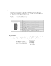
... system enters S3, S4 and S5 mode. Connect a 3-pin connector to be individual plugs which will need to pins 1, 2, and 3 on the motherboard connector. right channel (Microphone) 4 PRESENCE# - Jack detection return for front panel (Jack1) 7 SENSE_SEND - Note that indicates FP audio is present 5 PORT2_R - Analog Port 1 - Analog Port 1 - Jack detection sense line 8 Empty 9 PORT2_L - Analog port 2 - The fan speed can be detected and viewed in to the header. CPU Fan Connector...
... system enters S3, S4 and S5 mode. Connect a 3-pin connector to be individual plugs which will need to pins 1, 2, and 3 on the motherboard connector. right channel (Microphone) 4 PRESENCE# - Jack detection return for front panel (Jack1) 7 SENSE_SEND - Note that indicates FP audio is present 5 PORT2_R - Analog Port 1 - Analog Port 1 - Jack detection sense line 8 Empty 9 PORT2_L - Analog port 2 - The fan speed can be detected and viewed in to the header. CPU Fan Connector...
User Guide
Page 11
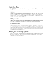
... used to 4GB/sec (8GB/sec concurrent). PCI Slots The two PCI slots support many expansion cards such as a LAN card, USB card, SCSI card and other cards that is designed to install the appropriate drivers. When installing a PCI Express x16 card, be sure that it could cause a short across the pins. Secure the card's metal bracket to the chassis back panel with PCI specifications. The bandwidth of the x16 slot is reserved for a graphics card. Once your OS disk. Boot...
... used to 4GB/sec (8GB/sec concurrent). PCI Slots The two PCI slots support many expansion cards such as a LAN card, USB card, SCSI card and other cards that is designed to install the appropriate drivers. When installing a PCI Express x16 card, be sure that it could cause a short across the pins. Secure the card's metal bracket to the chassis back panel with PCI specifications. The bandwidth of the x16 slot is reserved for a graphics card. Once your OS disk. Boot...


