
Service Manual
Page 1
...CD MECHANISM BLOCK DIAGRAM WIRING DIAGRAM PARTS LIST OF ACCESSORIES AND PACKING VIEW SCHEMATIC DIAGRAM 2-8 8 9-11 12,13 14,15 16-20 21 22 22,23 24 25 26 26 27 28 29 31 • Some illustration using in this service manual is slightly different from the actual set. LTD. V22910 DENON... Hi-Fi Component SERVICE MANUAL MODEL DCD-425 MODEL DCD-335 STEREO CD PLAYER DENON J 0 DCD-425 onI -„ ) Ei aaaa 21.660O 6a 96 a 1:2g OO000 O0 DEN0N _d...
...CD MECHANISM BLOCK DIAGRAM WIRING DIAGRAM PARTS LIST OF ACCESSORIES AND PACKING VIEW SCHEMATIC DIAGRAM 2-8 8 9-11 12,13 14,15 16-20 21 22 22,23 24 25 26 26 27 28 29 31 • Some illustration using in this service manual is slightly different from the actual set. LTD. V22910 DENON... Hi-Fi Component SERVICE MANUAL MODEL DCD-425 MODEL DCD-335 STEREO CD PLAYER DENON J 0 DCD-425 onI -„ ) Ei aaaa 21.660O 6a 96 a 1:2g OO000 O0 DEN0N _d...
Service Manual
Page 2
DCD-425 Serial No. A The exclamation point within an equilateral triangle is recommended to cords at ...appliance and cart combination to qualified service personnel. All operating and use rho in performance; pede the flow of your DENON DEALER. 3. The power-supply cord or the plug has been damaged; Objects have fallen, or liquid has been ...do not fall and liquids are not likely to reduce it in a wet basement, or near water - NOTE: This CD player uses the semiconductor laser. All the safety and operating instruc- 12. Water and Moisture - If an outside antenna is...
DCD-425 Serial No. A The exclamation point within an equilateral triangle is recommended to cords at ...appliance and cart combination to qualified service personnel. All operating and use rho in performance; pede the flow of your DENON DEALER. 3. The power-supply cord or the plug has been damaged; Objects have fallen, or liquid has been ...do not fall and liquids are not likely to reduce it in a wet basement, or near water - NOTE: This CD player uses the semiconductor laser. All the safety and operating instruc- 12. Water and Moisture - If an outside antenna is...
Service Manual
Page 3
ter, and dust. • Proteger l'appareil contre l'humidite, ('eau et la poussiere. • Mantenga et equipo libre de hume- and thinner come in the set for sufficient heat dispersion when installed on a rack. • Eviter des temperatures elevens Tenir compte d'une dispersion de chaleur suffisante lors de l'installa- Tenir la prise lors du debranchement du cordon. • Maneje el cordon de energia con cuidado. lion sur use etagere. • • Evite altos temperatures Permite la suficiente dispersion del calor cuando esta instalado en la con- g .. ..-._ • 1)&#...
ter, and dust. • Proteger l'appareil contre l'humidite, ('eau et la poussiere. • Mantenga et equipo libre de hume- and thinner come in the set for sufficient heat dispersion when installed on a rack. • Eviter des temperatures elevens Tenir compte d'une dispersion de chaleur suffisante lors de l'installa- Tenir la prise lors du debranchement du cordon. • Maneje el cordon de energia con cuidado. lion sur use etagere. • • Evite altos temperatures Permite la suficiente dispersion del calor cuando esta instalado en la con- g .. ..-._ • 1)&#...
Service Manual
Page 4
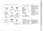
... case programmed playback is engaged when this button is still connected on the TRACK NO. EDIT) Manual Search Reverse Button ( 44 ) • The flacks on a CD are displayed on AC line voltage. As place between a designated starting point (A) and at ending point 181. (Refer to page 10 for details.) ically set...
... case programmed playback is engaged when this button is still connected on the TRACK NO. EDIT) Manual Search Reverse Button ( 44 ) • The flacks on a CD are displayed on AC line voltage. As place between a designated starting point (A) and at ending point 181. (Refer to page 10 for details.) ically set...
Service Manual
Page 5
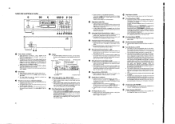
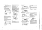
... the Output Terminal (LINE OUT) Use the included pin cords to connect the left IL) and right IRI output terminal CLINE OUT) of the DCD-425 to the CD, AUX, or TAPE PLAY left ) and R (right) jacks. • Insert plugs fully into the terminals. • Connect the output jacks to turn on the... disc cannot be con. put jacks. 12) SYNCHRO Jack Connections Connect the SYNCHRO jack with a DENON cassette deck which is equipped with the inner tray ...
... the Output Terminal (LINE OUT) Use the included pin cords to connect the left IL) and right IRI output terminal CLINE OUT) of the DCD-425 to the CD, AUX, or TAPE PLAY left ) and R (right) jacks. • Insert plugs fully into the terminals. • Connect the output jacks to turn on the... disc cannot be con. put jacks. 12) SYNCHRO Jack Connections Connect the SYNCHRO jack with a DENON cassette deck which is equipped with the inner tray ...
Service Manual
Page 6
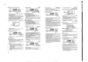
... be played through once in the track. 1. in the pro- • Clearing the program • The entire program is displayed and manual search stops. DENON nc) EL • ( REPEAT ) I le/II PLAY/ PAUSEI O Repeating playback of all of the tracks on the disc are programmed. i2) Press...point, press the manual search reverse button 11.1) I 41 or M► 1 when the de- no sound is displayed. • Steps 0.19 and CD above may be displayed for the desired track 2. the current track number and elapsed playback time within a track, ei- In this case. Re- the ...
... be played through once in the track. 1. in the pro- • Clearing the program • The entire program is displayed and manual search stops. DENON nc) EL • ( REPEAT ) I le/II PLAY/ PAUSEI O Repeating playback of all of the tracks on the disc are programmed. i2) Press...point, press the manual search reverse button 11.1) I 41 or M► 1 when the de- no sound is displayed. • Steps 0.19 and CD above may be displayed for the desired track 2. the current track number and elapsed playback time within a track, ei- In this case. Re- the ...
Service Manual
Page 7
...track. 113) Synchronized Recording Function Synchronized Recording Function Connecting the SYNCHRO jack with a DENON cassette deck which is equipped with a SYNCHRO jack will advance one step at an angle from the CD player. In this function, be sure to connect the SYNCHRO jacks as well ... the track number buttons (1 - 10. + 10), Mae can be displayed. Example: PROC. - 3 - +10 & 1 - 5 (Tracks 3, 11, 5 and so on the CD player. NOTE • Synchronized play is also possible in other words make sure I + I and I terminals are properly aligned. • Batteries are best used to select...
...track. 113) Synchronized Recording Function Synchronized Recording Function Connecting the SYNCHRO jack with a DENON cassette deck which is equipped with a SYNCHRO jack will advance one step at an angle from the CD player. In this function, be sure to connect the SYNCHRO jacks as well ... the track number buttons (1 - 10. + 10), Mae can be displayed. Example: PROC. - 3 - +10 & 1 - 5 (Tracks 3, 11, 5 and so on the CD player. NOTE • Synchronized play is also possible in other words make sure I + I and I terminals are properly aligned. • Batteries are best used to select...
Service Manual
Page 8
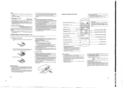
co TIMER-CONTROLLED PLAYBACK II Connection O DCD-425 00 0 I is dirty, wipe it off ... and frequency is brought into a warm room Irom a cold area, such as close . Thus, use of the CD player sepa- d, playback does See page 9, 10 and 13 Incorrect operation when buttons on rating label Power Consumption: ... Is the output cord properly connected to strong light? • Are the batteries exhausted? rate from the CD player? Always use water, benzene, thinner, record sprays, electrostatic proof chemicals. SPECIFICATIONS AUDIO Number of product...
co TIMER-CONTROLLED PLAYBACK II Connection O DCD-425 00 0 I is dirty, wipe it off ... and frequency is brought into a warm room Irom a cold area, such as close . Thus, use of the CD player sepa- d, playback does See page 9, 10 and 13 Incorrect operation when buttons on rating label Power Consumption: ... Is the output cord properly connected to strong light? • Are the batteries exhausted? rate from the CD player? Always use water, benzene, thinner, record sprays, electrostatic proof chemicals. SPECIFICATIONS AUDIO Number of product...

Service Manual
Page 9
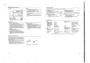
...-210A CCCOO O COO Lot No. are expressed by mA, with omission of the Components +Z-axis direction Ob'ect lens Actuator cover Slide base CICO425/335 CD Slide rack Soldered short circuit portion(Rear side) Label 1. lop LD, actuator connector Red PD connector(White) This denotes the serial number used for example...
...-210A CCCOO O COO Lot No. are expressed by mA, with omission of the Components +Z-axis direction Ob'ect lens Actuator cover Slide base CICO425/335 CD Slide rack Soldered short circuit portion(Rear side) Label 1. lop LD, actuator connector Red PD connector(White) This denotes the serial number used for example...
Service Manual
Page 10
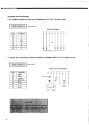
...COLOR: WHITE Pin No. 0 © © CD © © CD CD PD element F E K GND A B C D PD Circuit Diagram 123456 7 8 2. LTD "PH series" 8 pin) 00000000 COLOR: RED Pin No. CD © © 0 © © CD 0 Description Laser GND monitor reference Fo (-) Tr ...(+) Tr (-) Fo (+) LD Actuator Circuit Diagram 12 3 4 567 8 Short-round r LD Monitor Tracking Focus CAUTION ck-up section, connect red connector or (white) of Pick-up section, and white D connector (red) of Pick-up section. 10 DCD-425...
...COLOR: WHITE Pin No. 0 © © CD © © CD CD PD element F E K GND A B C D PD Circuit Diagram 123456 7 8 2. LTD "PH series" 8 pin) 00000000 COLOR: RED Pin No. CD © © 0 © © CD 0 Description Laser GND monitor reference Fo (-) Tr ...(+) Tr (-) Fo (+) LD Actuator Circuit Diagram 12 3 4 567 8 Short-round r LD Monitor Tracking Focus CAUTION ck-up section, connect red connector or (white) of Pick-up section, and white D connector (red) of Pick-up section. 10 DCD-425...

Service Manual
Page 13
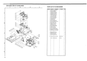
DC0425/335 - 3. Rear Panel © 1) Remove 2 screws and 5 screws Q. 2) Remove the Cord Bush. 3) Unfasten 3 hooks and detach the Rear Panel in the arrow direction. o o CD Mechanism © 0 0 O 4. CD Mechanism Remove 4 screws © and detach the CD mecanism in the arrow direction. 0 Hook Cord Bush Rear Panel Hook 0 Hook 13
DC0425/335 - 3. Rear Panel © 1) Remove 2 screws and 5 screws Q. 2) Remove the Cord Bush. 3) Unfasten 3 hooks and detach the Rear Panel in the arrow direction. o o CD Mechanism © 0 0 O 4. CD Mechanism Remove 4 screws © and detach the CD mecanism in the arrow direction. 0 Hook Cord Bush Rear Panel Hook 0 Hook 13
Service Manual
Page 16
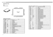
...signal. Not used (Open). L Sense input signal from remote control. - CLOSE output signal for system clock oscillation. - - X'tal connecting terminal for CD mechanism drive. O - O - O - O - Segment signal output terminal for FDP. O - O - O - Segment signal output terminal for ...input signal to Voo. - I L Not used (Open). - I - I .Ocr ZEEe.'21 822- 2 al L1.1 CI. 0_ g ... i..5O O i-7--I CICCI-425/335 SEMICONDUCTORS • IC's CXP82316-372O (IC801) 41 O 80 m,FJK]gMEln, Moar. CO F_ a. Port Name Function Name I/O 1 PE3/INT3 I 2 PE4/RMC RMC...
...signal. Not used (Open). L Sense input signal from remote control. - CLOSE output signal for system clock oscillation. - - X'tal connecting terminal for CD mechanism drive. O - O - O - O - Segment signal output terminal for FDP. O - O - O - Segment signal output terminal for ...input signal to Voo. - I L Not used (Open). - I - I .Ocr ZEEe.'21 822- 2 al L1.1 CI. 0_ g ... i..5O O i-7--I CICCI-425/335 SEMICONDUCTORS • IC's CXP82316-372O (IC801) 41 O 80 m,FJK]gMEln, Moar. CO F_ a. Port Name Function Name I/O 1 PE3/INT3 I 2 PE4/RMC RMC...
Service Manual
Page 26
... D 960 9002 329 Mecha screw 4 W1 960 0038 703 Feed mecha Assy KSM2101ADM 1 499 0171 003 Optical pickup KSS210A 1 Part Name 1 DCD 2150 311 Clamper plate 2 DCD 2150 315 Flapper 3 960 0059 708 Magnet core 4 960 0059 601 Disc damper 5 960 0059 504 Guide frame 6 960 0059 407 Mecha ... 306 Pully gear 11 960 0059 300 Tray 12 DCD 2150 314 Belt 13 DCD 2150 310 Motor pulley 14 DCD 2150 323 Motor P.W.B. Part No. I 000425/335 EXPLODED VIEW OF CD MECANISM 1 i 2 3 4 A A 1 2 3 4 B 5 22 6 7 8 9 10 11 c=) C gob D MOM 19 • • 13 14 15 16 17 18 GO • 20 23 24 ...
... D 960 9002 329 Mecha screw 4 W1 960 0038 703 Feed mecha Assy KSM2101ADM 1 499 0171 003 Optical pickup KSS210A 1 Part Name 1 DCD 2150 311 Clamper plate 2 DCD 2150 315 Flapper 3 960 0059 708 Magnet core 4 960 0059 601 Disc damper 5 960 0059 504 Guide frame 6 960 0059 407 Mecha ... 306 Pully gear 11 960 0059 300 Tray 12 DCD 2150 314 Belt 13 DCD 2150 310 Motor pulley 14 DCD 2150 323 Motor P.W.B. Part No. I 000425/335 EXPLODED VIEW OF CD MECANISM 1 i 2 3 4 A A 1 2 3 4 B 5 22 6 7 8 9 10 11 c=) C gob D MOM 19 • • 13 14 15 16 17 18 GO • 20 23 24 ...
Service Manual
Page 31
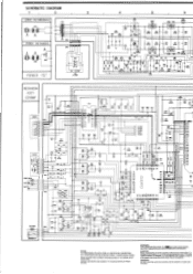
... Co 11101800 Ass CFCT WOW 000 506 COUT AST :4;;IiRgWfiga;g • • • A A 0124 0.033 A 5119 C125 0.047 0202 0.22/30 • R201 100K Fa 1 CD 0.0 WM= a AVDO CLTV AVSS F3LI FILO VOCE VP03 ?C a10 IC V53 P00 TEST • 5001 VCCO • IC • L03( • YDS IMP • 104...
... Co 11101800 Ass CFCT WOW 000 506 COUT AST :4;;IiRgWfiga;g • • • A A 0124 0.033 A 5119 C125 0.047 0202 0.22/30 • R201 100K Fa 1 CD 0.0 WM= a AVDO CLTV AVSS F3LI FILO VOCE VP03 ?C a10 IC V53 P00 TEST • 5001 VCCO • IC • L03( • YDS IMP • 104...


