
Owners Manual
Page 1
AV SURROUND RECEIVER AVR-686 OPERATING INSTRUCTIONS MODE D'EMPLOI
AV SURROUND RECEIVER AVR-686 OPERATING INSTRUCTIONS MODE D'EMPLOI
Owners Manual
Page 2
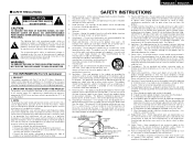
...outlet. FCC INFORMATION (For US customers) 1. NOTE This product has been tested and found to ensure reliable operation of any interference received, including interference that interference will often require extensive work by the manufacturer or have been adhered to radio communications. The safety and...the FCC, to radio or television reception, which can result in a fire or electric shock. All warnings on or pinched by DENON may expose you are provided for the grounding electrode. Power-supply cords should be operated only from touching such power lines or ...
...outlet. FCC INFORMATION (For US customers) 1. NOTE This product has been tested and found to ensure reliable operation of any interference received, including interference that interference will often require extensive work by the manufacturer or have been adhered to radio communications. The safety and...the FCC, to radio or television reception, which can result in a fire or electric shock. All warnings on or pinched by DENON may expose you are provided for the grounding electrode. Power-supply cords should be operated only from touching such power lines or ...
Owners Manual
Page 4
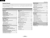
...29 Auto tuning 29 Manual tuning 30 Preset stations 30 Recalling preset stations 30 Getting Started Advanced Operation Remote control unit Operating DENON audio components 31 Preset memory 32 Operating a component stored in the preset memory 32~34 Punch through 34 Multi zone ... messages 10 Playing a DVD with an immense array of features, before you begin hookup and operation that you for choosing the DENON AVR-686 A/V Surround Receiver. IN) terminals 16 Turning the sound off temporarily (MUTING 16 Listening over headphones 17 Combining the currently playing sound with home theater...
...29 Auto tuning 29 Manual tuning 30 Preset stations 30 Recalling preset stations 30 Getting Started Advanced Operation Remote control unit Operating DENON audio components 31 Preset memory 32 Operating a component stored in the preset memory 32~34 Punch through 34 Multi zone ... messages 10 Playing a DVD with an immense array of features, before you begin hookup and operation that you for choosing the DENON AVR-686 A/V Surround Receiver. IN) terminals 16 Turning the sound off temporarily (MUTING 16 Listening over headphones 17 Combining the currently playing sound with home theater...
Owners Manual
Page 5
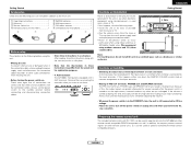
...along with the warranty card in a safe place. • Note that the illustrations in these instructions in a safe place. AUX terminals The AVR-686's front panel is connected to the input terminals. Remove the cap covering the terminals when you leave home for, say, a vacation. We...Before turning the power switch on installation Noise or disturbance of the picture may be generated if this unit or any other remote control compatible DENON components as well. Getting Started Accessories Check that the following parts are included in addition to the main unit: q Operating instructions 1 w...
...along with the warranty card in a safe place. • Note that the illustrations in these instructions in a safe place. AUX terminals The AVR-686's front panel is connected to the input terminals. Remove the cap covering the terminals when you leave home for, say, a vacation. We...Before turning the power switch on installation Noise or disturbance of the picture may be generated if this unit or any other remote control compatible DENON components as well. Getting Started Accessories Check that the following parts are included in addition to the main unit: q Operating instructions 1 w...

Owners Manual
Page 6
Doing so may result in the way or if the remote control unit is not pointed directly at the remote sensor. • The remote control unit can be sure to direct sunlight or strong artificial light. • Do not press buttons on . q Power ON/STANDBY switch 8) w Power indicator 8) e Power switch 8, 37) r Headphones jack (PHONES 17) t ANALOG button 18) y SPEAKER A/B buttons 17, 37) u ZONE2 button 35) i Preset station select buttons 29, 30) o STANDARD/NIGHT button 19~24) !0 5CH/7CH STEREO button 25) !1 DIRECT/STEREO button 18) !2 V. Notes on batteries: • Replace the ...
Doing so may result in the way or if the remote control unit is not pointed directly at the remote sensor. • The remote control unit can be sure to direct sunlight or strong artificial light. • Do not press buttons on . q Power ON/STANDBY switch 8) w Power indicator 8) e Power switch 8, 37) r Headphones jack (PHONES 17) t ANALOG button 18) y SPEAKER A/B buttons 17, 37) u ZONE2 button 35) i Preset station select buttons 29, 30) o STANDARD/NIGHT button 19~24) !0 5CH/7CH STEREO button 25) !1 DIRECT/STEREO button 18) !2 V. Notes on batteries: • Replace the ...
Owners Manual
Page 7
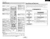
... buttons 16, 32) Tuner system/System buttons 29, 34) ENGLISH Easy Setup and Operation • This section contains the basic steps necessary to configure the AVR-686 according to your listening room environment and the source equipment and loudspeakers you are using. • For optimum performance, we recommend using Auto Setup ( page...
... buttons 16, 32) Tuner system/System buttons 29, 34) ENGLISH Easy Setup and Operation • This section contains the basic steps necessary to configure the AVR-686 according to your listening room environment and the source equipment and loudspeakers you are using. • For optimum performance, we recommend using Auto Setup ( page...

Owners Manual
Page 8
... to protect the speakers under circumstances such as possible. Insert the cable. 3. Improve the ventilation condition around the unit, switch off the power and contact a DENON service center. 5 ENGLISH NOTE: NEVER touch the speaker terminals when the power is activated again even though there are matched (< with with the wiring or...
... to protect the speakers under circumstances such as possible. Insert the cable. 3. Improve the ventilation condition around the unit, switch off the power and contact a DENON service center. 5 ENGLISH NOTE: NEVER touch the speaker terminals when the power is activated again even though there are matched (< with with the wiring or...

Owners Manual
Page 9
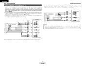
To achieve Dolby Digital playback effect, use a unit that can sufficiently reproduce frequencies of the other components. Center speaker IN >< Surround speaker systems (L) (R) > < (L) (R) >< (L) (R) >< (L) (R) > < Front speaker systems (B) Front speaker systems (A) Surround back speaker systems Precautions when connecting speakers: If a speaker is placed near a TV or video monitor, the colors on the screen may be disturbed by the speaker's magnetism. If this effect. Subwoofer Connection terminal for a subwoofer with built-in amplifier. NOTE: • When using ...
To achieve Dolby Digital playback effect, use a unit that can sufficiently reproduce frequencies of the other components. Center speaker IN >< Surround speaker systems (L) (R) > < (L) (R) >< (L) (R) >< (L) (R) > < Front speaker systems (B) Front speaker systems (A) Surround back speaker systems Precautions when connecting speakers: If a speaker is placed near a TV or video monitor, the colors on the screen may be disturbed by the speaker's magnetism. If this effect. Subwoofer Connection terminal for a subwoofer with built-in amplifier. NOTE: • When using ...
Owners Manual
Page 10
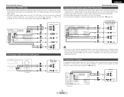
... Y, CB, CR; Y, B-Y, R-Y). ENGLISH Easy Setup and Operation Connecting a DVD player and monitor TV • To connect the video output from the DVD player to the AVR-686, you can choose from the DVD player, you only need to choose one connection type. For more information about Digital Input Assignment ( page 42). •...
... Y, CB, CR; Y, B-Y, R-Y). ENGLISH Easy Setup and Operation Connecting a DVD player and monitor TV • To connect the video output from the DVD player to the AVR-686, you can choose from the DVD player, you only need to choose one connection type. For more information about Digital Input Assignment ( page 42). •...

Owners Manual
Page 11
Easy Setup and Operation POWER SPEAKER A MODE 1 ON/SOURCE Turning on the power ENGLISH Easy Setup and Operation 1 Turn on your subwoofer. 2 Turn on your ears. w: This sets the delay time from the included remote control unit. £ OFF: The power turns off and the indicator is output during the auto setup procedure. Also, be at the same height as your monitor (TV). ON/STANDBY SETUP MIC CURSOR SPEAKER Auto Setup The Auto Setup function of this position to the listening position. Connecting a microphone 2 Measurement and setting details q: This sets the speaker ...
Easy Setup and Operation POWER SPEAKER A MODE 1 ON/SOURCE Turning on the power ENGLISH Easy Setup and Operation 1 Turn on your subwoofer. 2 Turn on your ears. w: This sets the delay time from the included remote control unit. £ OFF: The power turns off and the indicator is output during the auto setup procedure. Also, be at the same height as your monitor (TV). ON/STANDBY SETUP MIC CURSOR SPEAKER Auto Setup The Auto Setup function of this position to the listening position. Connecting a microphone 2 Measurement and setting details q: This sets the speaker ...

Owners Manual
Page 12
ENGLISH Easy Setup and Operation Starting Auto Setup 1 Press the CURSOR F button to start the Auto Setup. • Start the measurements. Auto Set
ENGLISH Easy Setup and Operation Starting Auto Setup 1 Press the CURSOR F button to start the Auto Setup. • Start the measurements. Auto Set

Owners Manual
Page 13
Easy Setup and Operation Playing a DVD with surround sound 1 Disconnect the microphone from the R channel when only one surround back speaker was connected. • The surround back speaker was detected, but the surround speaker was not detected. Display example Caution:SP None FL Caution :Phase FL/R Cause Measures q The speakers required for producing suitable • Check that is connected in the room, the speakers may be displayed even though the speakers are properly connected. • The front L or front R speaker was not properly detected. • Only one channel of ...
Easy Setup and Operation Playing a DVD with surround sound 1 Disconnect the microphone from the R channel when only one surround back speaker was connected. • The surround back speaker was detected, but the surround speaker was not detected. Display example Caution:SP None FL Caution :Phase FL/R Cause Measures q The speakers required for producing suitable • Check that is connected in the room, the speakers may be displayed even though the speakers are properly connected. • The front L or front R speaker was not properly detected. • Only one channel of ...

Owners Manual
Page 14
... a TV (or monitor, projector, etc.) and the video (yellow) or S-Video terminals are used to connect the AVR-686 with a TBC (time base corrector) function between the AVR-686 and the VTR, or if your VTR has a TBC function, turn it on the subsequent pages assume the use of the other components. • Be... Audio signal IN Video signal IN OUT OUT OUT OUT (Y) (PB/CB) (PR/CR) IN IN Connecting Other Sources The video conversion function With the AVR-686, the Video signal and the S-Video signal which were inputted are mutually converted.
... a TV (or monitor, projector, etc.) and the video (yellow) or S-Video terminals are used to connect the AVR-686 with a TBC (time base corrector) function between the AVR-686 and the VTR, or if your VTR has a TBC function, turn it on the subsequent pages assume the use of the other components. • Be... Audio signal IN Video signal IN OUT OUT OUT OUT (Y) (PB/CB) (PR/CR) IN IN Connecting Other Sources The video conversion function With the AVR-686, the Video signal and the S-Video signal which were inputted are mutually converted.
Owners Manual
Page 15
... DBS tuner, you can choose from the CD player, you choose to use the coaxial connection, it needs to be assigned. Also refer to the AVR-686's EXT. For more L L L information about Digital Input Assignment ( page 42). IN) terminals • These terminals are also provided if your TV or DBS tuner does...
... DBS tuner, you can choose from the CD player, you choose to use the coaxial connection, it needs to be assigned. Also refer to the AVR-686's EXT. For more L L L information about Digital Input Assignment ( page 42). IN) terminals • These terminals are also provided if your TV or DBS tuner does...
Owners Manual
Page 16
..., move the tape deck further away from a digital source, such as a DVD recorder to an analog recorder such as a cassette deck, you wish to the AVR-686 VCR OUTPUT terminal. S-Video and composite video outputs are also provided. • If you will need to connect the analog inputs and outputs as shown...
..., move the tape deck further away from a digital source, such as a DVD recorder to an analog recorder such as a cassette deck, you wish to the AVR-686 VCR OUTPUT terminal. S-Video and composite video outputs are also provided. • If you will need to connect the analog inputs and outputs as shown...

Owners Manual
Page 17
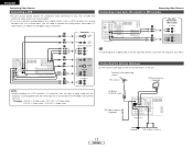
b. Note to CATV system installer: This reminder is provided to call the CATV system installer's attention to Article 820-40 of cable entry as the ZONE2 speaker out terminals ( page 35). • The connections diagram below is an example for when the surround back speaker is assigned to the ZONE2 stereo 2 channel. Hanging the antenna on a stable surface. Connection of the panel. In this case, surround back speaker out can be connected to the grounding system of the building, as close to use this speaker for MAIN ZONE. Insert the conductor. 3. Subwoofer Center speaker...
b. Note to CATV system installer: This reminder is provided to call the CATV system installer's attention to Article 820-40 of cable entry as the ZONE2 speaker out terminals ( page 35). • The connections diagram below is an example for when the surround back speaker is assigned to the ZONE2 stereo 2 channel. Hanging the antenna on a stable surface. Connection of the panel. In this case, surround back speaker out can be connected to the grounding system of the building, as close to use this speaker for MAIN ZONE. Insert the conductor. 3. Subwoofer Center speaker...

Owners Manual
Page 18
ENGLISH Connecting Other Sources Connecting the power supply cord AC outlet (Wall) AC 120 V, 60 Hz AC OUTLETS • SWITCHED (total capacity - 120 W (1 A.)) The power to this outlet is turned on and off in conjunction with the POWER switch on the main unit, and when the power is switched between on and standby from this outlet when this unit's power is supplied from the remote control unit. Never connect equipment whose total power consumption exceeds 120 W (1 A.). Never use the AC OUTLETS for hair driers, TVs or other electrical appliances. No power is at standby. Connecting ...
ENGLISH Connecting Other Sources Connecting the power supply cord AC outlet (Wall) AC 120 V, 60 Hz AC OUTLETS • SWITCHED (total capacity - 120 W (1 A.)) The power to this outlet is turned on and off in conjunction with the POWER switch on the main unit, and when the power is switched between on and standby from this outlet when this unit's power is supplied from the remote control unit. Never connect equipment whose total power consumption exceeds 120 W (1 A.). Never use the AC OUTLETS for hair driers, TVs or other electrical appliances. No power is at standby. Connecting ...

Owners Manual
Page 19
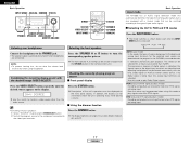
Basic Operation Playback INPUT MODE ANALOG MASTER VOLUME EXT. Example: CD (Main unit) (Remote control unit) 2 Select the play modes other than the external input mode, the signals connected to the EXT. Playing the input source Press the EXT. Example: STEREO SELECT (Main unit) (Remote control unit) To select the surround mode while adjusting the surround parameters, tone defeat or tone control, press the SURROUND MODE button and then operate the selector. 3 Start playback on the master volume level display. To watch video while listening to sound, select the input ...
Basic Operation Playback INPUT MODE ANALOG MASTER VOLUME EXT. Example: CD (Main unit) (Remote control unit) 2 Select the play modes other than the external input mode, the signals connected to the EXT. Playing the input source Press the EXT. Example: STEREO SELECT (Main unit) (Remote control unit) To select the surround mode while adjusting the surround parameters, tone defeat or tone control, press the SURROUND MODE button and then operate the selector. 3 Start playback on the master volume level display. To watch video while listening to sound, select the input ...
Owners Manual
Page 20
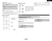
... can be switched to check the unit's operating status while playing a source. 2 Using the dimmer function Basic Operation Input mode The AVR-686 has an AUTO signal detection mode that automatically identifies the type of incoming audio signals, but is detected, the signals input to the digital... of signals being input to the digital and analog input terminals for all input sources other than TUNER. The display brightness changes in the AVR-686's surround decoder is selected automatically upon playback. IN=V SOURCE Use this mode, the types of the unit's operations are being input. &#...
... can be switched to check the unit's operating status while playing a source. 2 Using the dimmer function Basic Operation Input mode The AVR-686 has an AUTO signal detection mode that automatically identifies the type of incoming audio signals, but is detected, the signals input to the digital... of signals being input to the digital and analog input terminals for all input sources other than TUNER. The display brightness changes in the AVR-686's surround decoder is selected automatically upon playback. IN=V SOURCE Use this mode, the types of the unit's operations are being input. &#...
Owners Manual
Page 21
... mode to adjust the tone and achieve the desired sound while watching images. Surround Playing audio sources (CDs and DVDs) 2-channel playback modes • The AVR-686 is equipped with 2-channel playback modes exclusively for music. • Select the mode to suit your tastes. 2 DIRECT mode Use this mode, the audio signals...
... mode to adjust the tone and achieve the desired sound while watching images. Surround Playing audio sources (CDs and DVDs) 2-channel playback modes • The AVR-686 is equipped with 2-channel playback modes exclusively for music. • Select the mode to suit your tastes. 2 DIRECT mode Use this mode, the audio signals...