
Owner's Manual
Page 5
....book Page 5 Friday, October 27, 2006 4:02 PM Memory Problems 52 Mouse Problems 53 Network Problems 53 Power Problems 54...to read 59 3-D image quality is poor 59 4 Advanced Troubleshooting 61 Diagnostic Lights 61 Dell Diagnostics 64 When to Use the Dell Diagnostics 64 Drivers 67 What Is a Driver 67 Identifying Drivers 67 Reinstalling Drivers 67 Using ...Microsoft® Windows® XP System Restore 69 Creating a Restore Point 69 Restoring the Computer ...
....book Page 5 Friday, October 27, 2006 4:02 PM Memory Problems 52 Mouse Problems 53 Network Problems 53 Power Problems 54...to read 59 3-D image quality is poor 59 4 Advanced Troubleshooting 61 Diagnostic Lights 61 Dell Diagnostics 64 When to Use the Dell Diagnostics 64 Drivers 67 What Is a Driver 67 Identifying Drivers 67 Reinstalling Drivers 67 Using ...Microsoft® Windows® XP System Restore 69 Creating a Restore Point 69 Restoring the Computer ...

Owner's Manual
Page 6
... Work Inside Your Computer 75 Removing the Computer Cover 76 Inside View of Your Computer 78 System Board Components 79 Memory 80 DDR2 Memory Overview 80 Addressing Memory Configurations 82 Installing Memory 82 Removing Memory 84 Cards 84 Removing PCI and PCI Express Cards 85 Installing PCI and PCI Express Cards 87 Removing a PCI Express...
... Work Inside Your Computer 75 Removing the Computer Cover 76 Inside View of Your Computer 78 System Board Components 79 Memory 80 DDR2 Memory Overview 80 Addressing Memory Configurations 82 Installing Memory 82 Removing Memory 84 Cards 84 Removing PCI and PCI Express Cards 85 Installing PCI and PCI Express Cards 87 Removing a PCI Express...

Owner's Manual
Page 11
... your operating system and language, and then 3.5-inch USB floppy drives, Intel® Pentium® M search for components, such as the memory, hard drive, and operating system • Customer Care - Service call and order status, and warranty and repair information • Service and...or business segment to support.dell.com, select your business segment, and then enter your Dell computer. DSS is NOTE: The support.dell.com user interface may vary necessary for your selections. • How to use Windows XP • How to work with other Dell customers • Upgrades ...
... your operating system and language, and then 3.5-inch USB floppy drives, Intel® Pentium® M search for components, such as the memory, hard drive, and operating system • Customer Care - Service call and order status, and warranty and repair information • Service and...or business segment to support.dell.com, select your business segment, and then enter your Dell computer. DSS is NOTE: The support.dell.com user interface may vary necessary for your selections. • How to use Windows XP • How to work with other Dell customers • Upgrades ...
Owner's Manual
Page 15
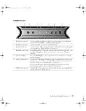
... that typically remain connected, such as printers and keyboards. 7 IEEE 1394a connector Use the IEEE 1394a connector for high-speed data devices such as flash memory keys, cameras, or bootable USB devices.
... that typically remain connected, such as printers and keyboards. 7 IEEE 1394a connector Use the IEEE 1394a connector for high-speed data devices such as flash memory keys, cameras, or bootable USB devices.

Owner's Manual
Page 18
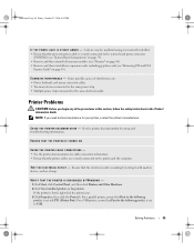
... high-speed data devices such as digital video cameras and external storage devices. CAUTION: Your computer is recommended that you connect occasionally, such as flash memory keys, cameras, or bootable USB devices. The LFE channel drives a subwoofer to attach multichannel-capable speakers. Use the (black) surround sound connector to provide extremely...
... high-speed data devices such as digital video cameras and external storage devices. CAUTION: Your computer is recommended that you connect occasionally, such as flash memory keys, cameras, or bootable USB devices. The LFE channel drives a subwoofer to attach multichannel-capable speakers. Use the (black) surround sound connector to provide extremely...

Owner's Manual
Page 33
... the CD or DVD playing. 1 Click Start, point to increase or decrease the volume. Adjusting the Volume NOTE: When the speakers are using too much memory and preventing DVD playback, adjust the display properties. 1 Click Start, then click Control Panel. 2 Under Pick a category, click Appearance and Themes. 3 Under Pick a task..., click...
... the CD or DVD playing. 1 Click Start, point to increase or decrease the volume. Adjusting the Volume NOTE: When the speakers are using too much memory and preventing DVD playback, adjust the display properties. 1 Click Start, then click Control Panel. 2 Under Pick a category, click Appearance and Themes. 3 Under Pick a task..., click...

Owner's Manual
Page 36
... Guide. Using a Media Card Reader (Optional) CAUTION: Before you record the project permanently to your computer. The media card reader supports the following memory types: • xD-Picture card • SmartMedia card (SMC) • CompactFlash card Type I and II (CF I/II) • MicroDrive... card • SecureDigital card (SD) • MiniSD card • MultiMediaCard (MMC) • Reduced-size MultiMediaCard (RS-MMC) • Memory Stick (MS/MS Pro/MS Duo/MS Pro Duo) For information on installing a media card reader, see "Installing a Media Card Reader" on the ...
... Guide. Using a Media Card Reader (Optional) CAUTION: Before you record the project permanently to your computer. The media card reader supports the following memory types: • xD-Picture card • SmartMedia card (SMC) • CompactFlash card Type I and II (CF I/II) • MicroDrive... card • SecureDigital card (SD) • MiniSD card • MultiMediaCard (MMC) • Reduced-size MultiMediaCard (RS-MMC) • Memory Stick (MS/MS Pro/MS Duo/MS Pro Duo) For information on installing a media card reader, see "Installing a Media Card Reader" on the ...

Owner's Manual
Page 37
... Page 37 Friday, October 27, 2006 4:02 PM 1 2 4 3 1 xD-Picture card and SmartMedia Card (SMC) 4 CompactFlash card Type I and II (CF I/II) and MicroDrive card 2 Memory Stick (MS/MS 3 Secure Digital card Pro/MS Duo/MS Pro Duo) (SD/miniSD)/MultiMedia- If you encounter resistance, remove the card, check for insertion...
... Page 37 Friday, October 27, 2006 4:02 PM 1 2 4 3 1 xD-Picture card and SmartMedia Card (SMC) 4 CompactFlash card Type I and II (CF I/II) and MicroDrive card 2 Memory Stick (MS/MS 3 Secure Digital card Pro/MS Duo/MS Pro Duo) (SD/miniSD)/MultiMedia- If you encounter resistance, remove the card, check for insertion...

Owner's Manual
Page 40
... click Stand by copying system data to a reserved area on the keyboard or moving the mouse does not bring the computer out of the computer memory, Dell creates an appropriately sized hibernate mode file before shipping the computer to store the contents of hibernation. To exit from hibernate mode, press the power... on the Power Schemes tab, Advanced tab, and Hibernate tab. 40 Setting Up and Using Your Computer If the computer's hard drive becomes corrupted, Windows XP recreates the hibernate file automatically.
... click Stand by copying system data to a reserved area on the keyboard or moving the mouse does not bring the computer out of the computer memory, Dell creates an appropriately sized hibernate mode file before shipping the computer to store the contents of hibernation. To exit from hibernate mode, press the power... on the Power Schemes tab, Advanced tab, and Hibernate tab. 40 Setting Up and Using Your Computer If the computer's hard drive becomes corrupted, Windows XP recreates the hibernate file automatically.

Owner's Manual
Page 52
...• Ensure that your computer. If necessary, install additional memory (see "Installing Memory" on page 82). • Reseat the memory modules (see "Memory" on page 80) to ensure that your computer, see "Memory" on page 129. • Run the Dell Diagnostics (see if that resolves the problem. • See...Before you begin any open programs you are not using is supported by your computer is successfully communicating with the memory. • Run the Dell Diagnostics (see "Dell Diagnostics" on page 64). book.book Page 52 Friday, October 27, 2006 4:02 PM Other software problems ...
...• Ensure that your computer. If necessary, install additional memory (see "Installing Memory" on page 82). • Reseat the memory modules (see "Memory" on page 80) to ensure that your computer, see "Memory" on page 129. • Run the Dell Diagnostics (see if that resolves the problem. • See...Before you begin any open programs you are not using is supported by your computer is successfully communicating with the memory. • Run the Dell Diagnostics (see "Dell Diagnostics" on page 64). book.book Page 52 Friday, October 27, 2006 4:02 PM Other software problems ...
Owner's Manual
Page 55
... set to the system board power connector (POWER2) (see "System Board Components" on page 79). • Remove and then reinstall all memory modules (see "Removing PCI and PCI Express Cards" on page 80). • Remove and then reinstall any of interference are securely connected ... Printers and Other Hardware. 2 Click View installed printers or fax printers. NOTE: If you begin any expansion cards, including graphics cards (see "Memory" on page 85). A device may be malfunctioning or incorrectly installed. • Ensure that Print to the following port(s): is listed, right-click...
... set to the system board power connector (POWER2) (see "System Board Components" on page 79). • Remove and then reinstall all memory modules (see "Removing PCI and PCI Express Cards" on page 80). • Remove and then reinstall any of interference are securely connected ... Printers and Other Hardware. 2 Click View installed printers or fax printers. NOTE: If you begin any expansion cards, including graphics cards (see "Memory" on page 85). A device may be malfunctioning or incorrectly installed. • Ensure that Print to the following port(s): is listed, right-click...

Owner's Manual
Page 61
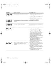
...If the computer malfunctions, the sequence of the lights help troubleshoot a problem, your computer (see "Installing Memory" on page 82). • If the problem persists, contact Dell (see "Installing Memory" on page 147). A possible processor failure has occurred. • Reseat the processor (see "Processor... to identify the problem. To help to install additional memory modules (one module (see "Contacting Dell" on page 13). Memory modules are detected, but a memory failure has occurred. • If two or more memory modules are not lit after the system successfully boots to...
...If the computer malfunctions, the sequence of the lights help troubleshoot a problem, your computer (see "Installing Memory" on page 82). • If the problem persists, contact Dell (see "Installing Memory" on page 147). A possible processor failure has occurred. • Reseat the processor (see "Processor... to identify the problem. To help to install additional memory modules (one module (see "Contacting Dell" on page 13). Memory modules are detected, but a memory failure has occurred. • If two or more memory modules are not lit after the system successfully boots to...
Owner's Manual
Page 62
... occurred. • Reseat any installed graphics cards (see "Cards" on page 84). • If available, install a working memory of the same type into your computer. • If the problem persists, contact Dell (see "Contacting Dell" on page 147). A possible floppy drive or hard drive failure has Reseat all cable connections. Reinstall all USB...
... occurred. • Reseat any installed graphics cards (see "Cards" on page 84). • If available, install a working memory of the same type into your computer. • If the problem persists, contact Dell (see "Contacting Dell" on page 147). A possible floppy drive or hard drive failure has Reseat all cable connections. Reinstall all USB...

Owner's Manual
Page 66
If you to run from system setup, memory, and various internal tests, and it appears and follow the instructions on page 147). The Dell Diagnostics obtains configuration information for all devices attached to customize the test, if applicable, by changing the test settings. 66 Advanced Troubleshooting ... you are having. The following tabs provide additional information for running the test. Lists a number of each test screen. When contacting Dell support, have your computer is located at the top of common symptoms and allows you cannot resolve the problem, contact...
If you to run from system setup, memory, and various internal tests, and it appears and follow the instructions on page 147). The Dell Diagnostics obtains configuration information for all devices attached to customize the test, if applicable, by changing the test settings. 66 Advanced Troubleshooting ... you are having. The following tabs provide additional information for running the test. Lists a number of each test screen. When contacting Dell support, have your computer is located at the top of common symptoms and allows you cannot resolve the problem, contact...

Owner's Manual
Page 79
otherwise these must be left empty front I/O panel connector 6 (FRONTPANEL) hard drive fan connector (FAN_HDD) back LED connector Removing and Installing Parts 79 book.book Page 79 Friday, October 27, 2006 4:02 PM System Board Components 1 2 3 4 27 26 5 6 7 8 9 10 11 12 25 24 23 22 21 20 19 13 14 15 16 17 18 1 white memory module 2 connectors (DIMM_1-2) support memory modules or memory module risers 4 IDE drive connector (IDE) 5 black memory module 3 connectors (DIMM_3-4) support memory modules only when no memory riser cards are installed;
otherwise these must be left empty front I/O panel connector 6 (FRONTPANEL) hard drive fan connector (FAN_HDD) back LED connector Removing and Installing Parts 79 book.book Page 79 Friday, October 27, 2006 4:02 PM System Board Components 1 2 3 4 27 26 5 6 7 8 9 10 11 12 25 24 23 22 21 20 19 13 14 15 16 17 18 1 white memory module 2 connectors (DIMM_1-2) support memory modules or memory module risers 4 IDE drive connector (IDE) 5 black memory module 3 connectors (DIMM_3-4) support memory modules only when no memory riser cards are installed;
Owner's Manual
Page 80
...25 liquid cooling assembly (TEC_PUMP) 26 processor (CPU) 27 processor fan connector (FAN1_CPU) Memory You can increase your computer memory by your computer, see "Memory" on page 129. If the DDR2 memory modules are not installed in performance. For additional information on the type of the module to...the computer will continue to determine the module's capacity. DDR2 Memory Overview • DDR2 memory modules should be installed in the order indicated on the upper-right or upper-left corner of memory supported by installing memory modules on the system board. See the label on the ...
...25 liquid cooling assembly (TEC_PUMP) 26 processor (CPU) 27 processor fan connector (FAN1_CPU) Memory You can increase your computer memory by your computer, see "Memory" on page 129. If the DDR2 memory modules are not installed in performance. For additional information on the type of the module to...the computer will continue to determine the module's capacity. DDR2 Memory Overview • DDR2 memory modules should be installed in the order indicated on the upper-right or upper-left corner of memory supported by installing memory modules on the system board. See the label on the ...

Owner's Manual
Page 81
... securing clips) NOTICE: If you purchased the new modules from any other connector. . Otherwise, your computer warranty. NOTE: Memory purchased from Dell is covered under your computer may have, even if you remove your original memory modules in pairs either in DIMM connectors 1 and 2 or - book.book Page 81 Friday, October 27, 2006...
... securing clips) NOTICE: If you purchased the new modules from any other connector. . Otherwise, your computer warranty. NOTE: Memory purchased from Dell is covered under your computer may have, even if you remove your original memory modules in pairs either in DIMM connectors 1 and 2 or - book.book Page 81 Friday, October 27, 2006...

Owner's Manual
Page 82
...27, 2006 4:02 PM Addressing Memory Configurations If you are using a 64-bit operating system, your computer will support a maximum of 8 GB (2-GB DIMMs in the Product Information Guide. If you begin any of the memory module connector. 1 2 1 memory connector closest to internal components, ...ground yourself by using a 32-bit operating system such as Microsoft® Windows® XP, your computer will support a maximum of 4 GB of memory. Installing Memory CAUTION: Before you are using a wrist grounding strap or by periodically touching an unpainted metal surface on...
...27, 2006 4:02 PM Addressing Memory Configurations If you are using a 64-bit operating system, your computer will support a maximum of 8 GB (2-GB DIMMs in the Product Information Guide. If you begin any of the memory module connector. 1 2 1 memory connector closest to internal components, ...ground yourself by using a 32-bit operating system such as Microsoft® Windows® XP, your computer will support a maximum of 4 GB of memory. Installing Memory CAUTION: Before you are using a wrist grounding strap or by periodically touching an unpainted metal surface on...

Owner's Manual
Page 83
... Align the notch on the bottom of the module with the crossbar in the connector. 3 2 1 4 1 cutouts (2) 4 crossbar 2 memory module 3 notch NOTICE: To avoid damage to the memory module, press the module straight down into the connector while you insert the module correctly, the securing clips snap into the... until the module snaps into the computer. 7 Connect your Windows desktop and click Properties. 11 Click the General tab. 12 To verify that memory size has changed, press to continue. 9 Log on page 127). Removing and Installing Parts 83 NOTICE: To connect a network cable, first...
... Align the notch on the bottom of the module with the crossbar in the connector. 3 2 1 4 1 cutouts (2) 4 crossbar 2 memory module 3 notch NOTICE: To avoid damage to the memory module, press the module straight down into the connector while you insert the module correctly, the securing clips snap into the... until the module snaps into the computer. 7 Connect your Windows desktop and click Properties. 11 Click the General tab. 12 To verify that memory size has changed, press to continue. 9 Log on page 127). Removing and Installing Parts 83 NOTICE: To connect a network cable, first...

Owner's Manual
Page 84
...8226; One PCI Express x8 card slot • One PCI Express x1 card slot NOTE: If a graphics card is installed in each of the memory module connector. 3 Grasp the module and pull up. Cards CAUTION: Before you begin any of the procedures in this section, follow the safety ...instructions in the Product Information Guide. Your Dell™ computer provides the following slots for use. 84 Removing and Installing Parts NOTICE: To avoid electrostatic discharge and damage to remove it ...
...8226; One PCI Express x8 card slot • One PCI Express x1 card slot NOTE: If a graphics card is installed in each of the memory module connector. 3 Grasp the module and pull up. Cards CAUTION: Before you begin any of the procedures in this section, follow the safety ...instructions in the Product Information Guide. Your Dell™ computer provides the following slots for use. 84 Removing and Installing Parts NOTICE: To avoid electrostatic discharge and damage to remove it ...


