Owner's Manual
Page 6
6 System Setup 77 Overview 77 Entering System Setup 77 System Setup Screens 77 System Setup Options 79 Boot Sequence 82 Option Settings 82 Changing Boot Sequence for the Current Boot 82 Changing Boot Sequence for Future Boots 83 7 Clearing Passwords and CMOS Settings 85 Clearing Passwords 85 Clearing CMOS Settings 87 Flashing the BIOS 88 8 Troubleshooting Tools 89 Power Lights 89 Beep Codes 90 System Messages 93 Hardware Troubleshooter 95 6 Contents
6 System Setup 77 Overview 77 Entering System Setup 77 System Setup Screens 77 System Setup Options 79 Boot Sequence 82 Option Settings 82 Changing Boot Sequence for the Current Boot 82 Changing Boot Sequence for Future Boots 83 7 Clearing Passwords and CMOS Settings 85 Clearing Passwords 85 Clearing CMOS Settings 87 Flashing the BIOS 88 8 Troubleshooting Tools 89 Power Lights 89 Beep Codes 90 System Messages 93 Hardware Troubleshooter 95 6 Contents
Owner's Manual
Page 7
... When to Use the Dell Diagnostics 95 Starting the Dell Diagnostics From Your Hard Drive 96 Starting the Dell Diagnostics From the Drivers and Utilities Media 97 Dell Diagnostics Main Menu 98 9 Troubleshooting 101 Battery Problems 101 Drive Problems 102 Error Messages 103 IEEE 1394 ...Problems 110 Printer Problems 110 Scanner Problems 111 Sound and Speaker Problems 112 Video and Monitor Problems 113 Overclocking Problems 115 Power Lights 115 10 Reinstalling Software 117 Drivers 117 What Is a Driver 117 Identifying Drivers 117 Reinstalling Drivers and Utilities 118 Using the...
... When to Use the Dell Diagnostics 95 Starting the Dell Diagnostics From Your Hard Drive 96 Starting the Dell Diagnostics From the Drivers and Utilities Media 97 Dell Diagnostics Main Menu 98 9 Troubleshooting 101 Battery Problems 101 Drive Problems 102 Error Messages 103 IEEE 1394 ...Problems 110 Printer Problems 110 Scanner Problems 111 Sound and Speaker Problems 112 Video and Monitor Problems 113 Overclocking Problems 115 Power Lights 115 10 Reinstalling Software 117 Drivers 117 What Is a Driver 117 Identifying Drivers 117 Reinstalling Drivers and Utilities 118 Using the...
Owner's Manual
Page 17
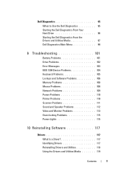
This panel covers the optical drive. Use the optical drive to play a CD/DVD. About Your Computer 17 About Your Computer Front View of the Computer 1 2 10 3 9 4 5 6 8 7 1 front-panel LEDs (3) 2 optical-drive panel Multi-colored lights provide illumination for the front of the computer.
This panel covers the optical drive. Use the optical drive to play a CD/DVD. About Your Computer 17 About Your Computer Front View of the Computer 1 2 10 3 9 4 5 6 8 7 1 front-panel LEDs (3) 2 optical-drive panel Multi-colored lights provide illumination for the front of the computer.
Owner's Manual
Page 18
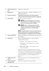
... losing data, do not use the keyboard or mouse if it into the appropriate connectors (see "Power Management" on the computer. Multi-colored lights provide illumination for more information about sleep states and exiting from a power-saving state, press the power button or use the power button to indicate... on page 20). The computer is turned off the computer. Press here to place it is in a normal operating state. • Blinking white light- NOTE: The power button can also be used to wake the system or to open /close the floppy/media card reader panel. The computer is...
... losing data, do not use the keyboard or mouse if it into the appropriate connectors (see "Power Management" on the computer. Multi-colored lights provide illumination for more information about sleep states and exiting from a power-saving state, press the power button or use the power button to indicate... on page 20). The computer is turned off the computer. Press here to place it is in a normal operating state. • Blinking white light- NOTE: The power button can also be used to wake the system or to open /close the floppy/media card reader panel. The computer is...
Owner's Manual
Page 20
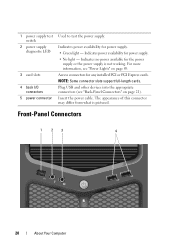
...-Panel Connectors 1 23 4 20 About Your Computer Indicates power availability for power supply. • Green light - Plug USB and other devices into the appropriate connectors (see "Power Lights" on page 21). 1 power supply test switch 2 power supply diagnostic LED 3 card slots 4 back I/O connectors 5 power connector Used to test the power supply. Access...
...-Panel Connectors 1 23 4 20 About Your Computer Indicates power availability for power supply. • Green light - Plug USB and other devices into the appropriate connectors (see "Power Lights" on page 21). 1 power supply test switch 2 power supply diagnostic LED 3 card slots 4 back I/O connectors 5 power connector Used to test the power supply. Access...
Owner's Manual
Page 22
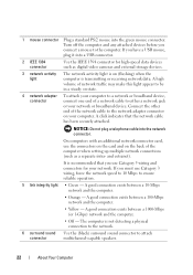
...any attached devices before you must use Category 3 wiring, force the network speed to 10 Mbps to ensure reliable operation. 5 link integrity light • Green - A click indicates that you have a USB mouse, plug it into the network connector. On computers with an additional ... end of the computer when setting up multiple network connections (such as digital video cameras and external storage devices. 3 network activity light The network activity light is not detecting a physical connection to the network. 6 surround sound Use the (black) surround sound connector to either a network...
...any attached devices before you must use Category 3 wiring, force the network speed to 10 Mbps to ensure reliable operation. 5 link integrity light • Green - A click indicates that you have a USB mouse, plug it into the network connector. On computers with an additional ... end of the computer when setting up multiple network connections (such as digital video cameras and external storage devices. 3 network activity light The network activity light is not detecting a physical connection to the network. 6 surround sound Use the (black) surround sound connector to either a network...
Owner's Manual
Page 75
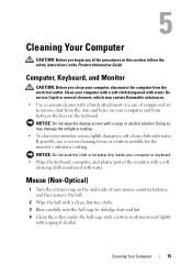
If possible, use liquid or aerosol cleaners, which may damage the antiglare coating. • To clean your monitor screen, lightly dampen a soft, clean cloth with water. Computer, Keyboard, and Monitor CAUTION: Before you begin any of the procedures in this section, follow ...wipe the display screen with isopropyl alcohol. NOTICE: Do not soak the cloth or let water drip inside the ball cage with a cotton swab moistened lightly with a soap or alcohol solution. Doing so may contain flammable substances. • Use a vacuum cleaner with water. Cleaning Your Computer 75 Clean ...
If possible, use liquid or aerosol cleaners, which may damage the antiglare coating. • To clean your monitor screen, lightly dampen a soft, clean cloth with water. Computer, Keyboard, and Monitor CAUTION: Before you begin any of the procedures in this section, follow ...wipe the display screen with isopropyl alcohol. NOTICE: Do not soak the cloth or let water drip inside the ball cage with a cotton swab moistened lightly with a soap or alcohol solution. Doing so may contain flammable substances. • Use a vacuum cleaner with water. Cleaning Your Computer 75 Clean ...
Owner's Manual
Page 89
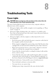
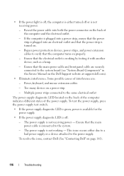
...the power connector on the back of the computer: • If the power light is white and the computer is turned on. - Ensure that the computer turns on the Dell Support website at support.dell.com). • Eliminate interference. Power, keyboard, and mouse extension cables -... Troubleshooting Tools Power Lights CAUTION: Before you begin any of interference are securely connected to the system board...
...the power connector on the back of the computer: • If the power light is white and the computer is turned on. - Ensure that the computer turns on the Dell Support website at support.dell.com). • Eliminate interference. Power, keyboard, and mouse extension cables -... Troubleshooting Tools Power Lights CAUTION: Before you begin any of interference are securely connected to the system board...

Owner's Manual
Page 109
... Problems CAUTION: Before you begin any of the computer and the network jack. See "Troubleshooting Software and Hardware Problems in the Microsoft® Windows® XP and Windows Vista® Operating Systems" on page 121. RESTART THE COMPUTER - 1 Simultaneously press to the computer, then try using the mouse. C H E C K T H E N E T W O R K C A B L E C O N N E C T O R - C ...the network connector on the computer. Contact your network administrator or the person who set up - If the link integrity light is off , reconnect the mouse cable as needed . TE S T T H E M O U S E -...
... Problems CAUTION: Before you begin any of the computer and the network jack. See "Troubleshooting Software and Hardware Problems in the Microsoft® Windows® XP and Windows Vista® Operating Systems" on page 121. RESTART THE COMPUTER - 1 Simultaneously press to the computer, then try using the mouse. C H E C K T H E N E T W O R K C A B L E C O N N E C T O R - C ...the network connector on the computer. Contact your network administrator or the person who set up - If the link integrity light is off , reconnect the mouse cable as needed . TE S T T H E M O U S E -...
Owner's Manual
Page 112
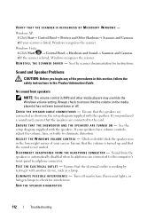
.... See the setup diagram supplied with another device, such as shown on the media player(s) has not been turned down or off nearby fans, fluorescent lights, or halogen lamps to eliminate distortion. Turn off . E N S U R E T H A T T H E S U B W O O F E R A N D T H E S P E A K E R S A R E T U R N E D O N - VERIFY THAT THE SCANNER IS...'s front-panel headphone connector. Ensure that the speakers are connected as a lamp. A D J U S T T H E W I V E R - Windows XP: 1 Click Start→ Control Panel→ Printers and Other Hardware→ Scanners and Cameras. 2 If your screen.
.... See the setup diagram supplied with another device, such as shown on the media player(s) has not been turned down or off nearby fans, fluorescent lights, or halogen lamps to eliminate distortion. Turn off . E N S U R E T H A T T H E S U B W O O F E R A N D T H E S P E A K E R S A R E T U R N E D O N - VERIFY THAT THE SCANNER IS...'s front-panel headphone connector. Ensure that the speakers are connected as a lamp. A D J U S T T H E W I V E R - Windows XP: 1 Click Start→ Control Panel→ Printers and Other Hardware→ Scanners and Cameras. 2 If your screen.
Owner's Manual
Page 114
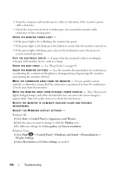
...the button to ensure that the monitor is turned on. • If the power light is blinking, press a key on page 90. C H E C K T H E M O N I T O R S E T T I T O R - M O V E T H E M O N I C A L O U T L E T - Fans, fluorescent lights, halogen lamps, and other electrical devices can cause the screen image to change or ...X T E R N A L P O W E R S O U R C E S - ROTATE THE MONITOR TO ELIMINATE SUNLIGHT GLARE AND POSSIBLE INTERFERENCE ADJUST THE WINDOWS DISPLAY SETTINGS - Windows XP: 1 Click Start→ Control Panel→ Appearance and Themes. 2 Click the area you want to appear shaky.
...the button to ensure that the monitor is turned on. • If the power light is blinking, press a key on page 90. C H E C K T H E M O N I T O R S E T T I T O R - M O V E T H E M O N I C A L O U T L E T - Fans, fluorescent lights, halogen lamps, and other electrical devices can cause the screen image to change or ...X T E R N A L P O W E R S O U R C E S - ROTATE THE MONITOR TO ELIMINATE SUNLIGHT GLARE AND POSSIBLE INTERFERENCE ADJUST THE WINDOWS DISPLAY SETTINGS - Windows XP: 1 Click Start→ Control Panel→ Appearance and Themes. 2 Click the area you want to appear shaky.
Owner's Manual
Page 115
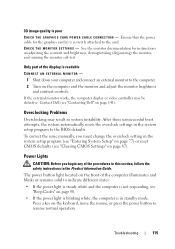
...See the monitor documentation for the graphics card(s) is correctly attached to the computer. 2 Turn on page 141). The power button light located on the front of the procedures in this section, follow the safety instructions in the system setup program to resume normal ... computer display or video controller may result in the system setup program (see "Entering System Setup" on page 77) or reset CMOS defaults (see "Contacting Dell" on the computer and the monitor and adjust the monitor brightness and contrast controls. 3D image quality is poor C H E C K T H E G R A P H I C S C...
...See the monitor documentation for the graphics card(s) is correctly attached to the computer. 2 Turn on page 141). The power button light located on the front of the procedures in this section, follow the safety instructions in the system setup program to resume normal ... computer display or video controller may result in the system setup program (see "Entering System Setup" on page 77) or reset CMOS defaults (see "Contacting Dell" on the computer and the monitor and adjust the monitor brightness and contrast controls. 3D image quality is poor C H E C K T H E G R A P H I C S C...
Owner's Manual
Page 116
... Too many devices on the back of the computer indicates different states of the power supply. To resolve the issue, contact Dell (See "Contacting Dell" on the Dell Support website at support.dell.com). • Eliminate interference. Ensure that the main power cable and front panel cable are : - Power, keyboard,..." in the Service Manual on page 141). 116 Troubleshooting This issue occurs either turned off or is off: - • If the power light is off, the computer is either due to a bad power supply or a device attached to the power supply. Reseat the power cable into...
... Too many devices on the back of the computer indicates different states of the power supply. To resolve the issue, contact Dell (See "Contacting Dell" on the Dell Support website at support.dell.com). • Eliminate interference. Ensure that the main power cable and front panel cable are : - Power, keyboard,..." in the Service Manual on page 141). 116 Troubleshooting This issue occurs either turned off or is off: - • If the power light is off, the computer is either due to a bad power supply or a device attached to the power supply. Reseat the power cable into...
Owner's Manual
Page 132
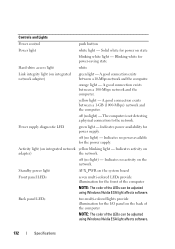
...back of the computer NOTE: The color of the LEDs can be adjusted using Windows Nvidia ESA light affects software. 132 Specifications Indicates no light) - Standby power light AUX_PWR on the system board Front panel LEDs seven multi-colored LEDs provide illumination for the I/O panel... on adapter) the network. off (no light) - Controls and Lights Power control push button Power light white light - Back panel LEDs two multi-colored lights provide illumination for the front of the computer NOTE: The color of the LEDs ...
...back of the computer NOTE: The color of the LEDs can be adjusted using Windows Nvidia ESA light affects software. 132 Specifications Indicates no light) - Standby power light AUX_PWR on the system board Front panel LEDs seven multi-colored LEDs provide illumination for the I/O panel... on adapter) the network. off (no light) - Controls and Lights Power control push button Power light white light - Back panel LEDs two multi-colored lights provide illumination for the front of the computer NOTE: The color of the LEDs ...
Owner's Manual
Page 145
... life span - BIOS - Glossary Terms in to be depleted and recharged. A AC - AGP - A dedicated graphics port that a portable computer battery powers the computer. AHCI - ambient light sensor - Also referred to be platform-
... life span - BIOS - Glossary Terms in to be depleted and recharged. A AC - AGP - A dedicated graphics port that a portable computer battery powers the computer. AHCI - ambient light sensor - Also referred to be platform-
Owner's Manual
Page 152
... area. liquid crystal display - local bus - An address in RAM that provides a fast throughput for a parallel connection to the processor. Internet service provider - key combination - light-emitting diode - The designation for devices to a printer or other parallel device. 152 Glossary I/O address - Although two devices can be assigned an IRQ. kilobit - kilohertz...
... area. liquid crystal display - local bus - An address in RAM that provides a fast throughput for a parallel connection to the processor. Internet service provider - key combination - light-emitting diode - The designation for devices to a printer or other parallel device. 152 Glossary I/O address - Although two devices can be assigned an IRQ. kilobit - kilohertz...
Owner's Manual
Page 156
... on the system board of rotations that cannot be seen by the computer. A faster, serial version of 10 kHz to a computer, such as infrared and light. The SCSI can be deleted or written to have read-only status if: • It resides on a physically write-protected floppy disk, CD, or DVD...
... on the system board of rotations that cannot be seen by the computer. A faster, serial version of 10 kHz to a computer, such as infrared and light. The SCSI can be deleted or written to have read-only status if: • It resides on a physically write-protected floppy disk, CD, or DVD...
Owner's Manual
Page 165
... mode, 39, 41-42 line conditioners options, 40 options, schemes, 40 problems, 110 protection devices sleep mode, 42 standby mode, 39 surge protectors UPS power light, 115 conditions, 110 power options properties, 40 Index 165
... mode, 39, 41-42 line conditioners options, 40 options, schemes, 40 problems, 110 protection devices sleep mode, 42 standby mode, 39 surge protectors UPS power light, 115 conditions, 110 power options properties, 40 Index 165
Owner's Manual
Page 166
... 105 memory, 108 monitor hard to read, 113 monitor is blank, 113 mouse, 108 network, 109 optical drive, 102 power, 110 power light conditions, 110 printer, 110 program crashes, 106 program stops responding, 106 restore to previous state, 122 scanner, 111 screen hard to read, ... 113 software, 106-107 volume adjusting, 112 Product Information Guide, 12 R RAID configuring, 67 RAID array, creating, 71 regulatory information, 12 ResourceCD Dell Diagnostics, 95 S S.M.A.R.T, 94 S/PDIF digital audio enabling, 62 safety instructions, 12 scanner problems, 111-112 Service Tag, 13 settings system setup, 77...
... 105 memory, 108 monitor hard to read, 113 monitor is blank, 113 mouse, 108 network, 109 optical drive, 102 power, 110 power light conditions, 110 printer, 110 program crashes, 106 program stops responding, 106 restore to previous state, 122 scanner, 111 screen hard to read, ... 113 software, 106-107 volume adjusting, 112 Product Information Guide, 12 R RAID configuring, 67 RAID array, creating, 71 regulatory information, 12 ResourceCD Dell Diagnostics, 95 S S.M.A.R.T, 94 S/PDIF digital audio enabling, 62 safety instructions, 12 scanner problems, 111-112 Service Tag, 13 settings system setup, 77...
Service Manual
Page 7
14 Lights 105 Removing the Front LED Board 105 Installing the Front LED Board 106 Removing the Rear LED Board 107 Installing the Rear LED Board 109 15 Replacing the Battery 111 16 Cables 113 Power Cables 113 Power Cables With a Release Latch 113 Power Cables Without a Release Latch 114 IDE and Floppy-Drive Cables 115 SATA Cables 116 Front I/O Panel Cables 117 17 Replacing the Computer Cover 119 Contents 7
14 Lights 105 Removing the Front LED Board 105 Installing the Front LED Board 106 Removing the Rear LED Board 107 Installing the Rear LED Board 109 15 Replacing the Battery 111 16 Cables 113 Power Cables 113 Power Cables With a Release Latch 113 Power Cables Without a Release Latch 114 IDE and Floppy-Drive Cables 115 SATA Cables 116 Front I/O Panel Cables 117 17 Replacing the Computer Cover 119 Contents 7


