User Manual
Page 2
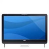
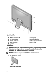
Figure 2. cooling vents 7. optical-drive eject button 9. For additional best practices information, see www.dell.com/regulatory_compliance. Back View 1. power connector 5. rear stand Quick Setup 6. Set up the rear stand. Rear Stand setup 2 NOTE: Some devices may not be included if you begin any of the procedures in this section, read the safety information that shipped with your computer. Figure 3. USB 2.0 connectors (4) 2. optical drive WARNING: Before you did not order them. 1. security cable slot 8. line-out connector 3. network connector 4.
Figure 2. cooling vents 7. optical-drive eject button 9. For additional best practices information, see www.dell.com/regulatory_compliance. Back View 1. power connector 5. rear stand Quick Setup 6. Set up the rear stand. Rear Stand setup 2 NOTE: Some devices may not be included if you begin any of the procedures in this section, read the safety information that shipped with your computer. Figure 3. USB 2.0 connectors (4) 2. optical drive WARNING: Before you did not order them. 1. security cable slot 8. line-out connector 3. network connector 4.


