Setup and Quick Reference Guide
Page 29
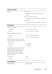
...: • minimum 2.1 kg (4.630 lb) with 4-cell battery Vostro 1510 and Vostro 2510: • minimum 2.6 kg (5.72 lb) with 6-cell battery Vostro 1710: • minimum 3.41kg (7.51 lb) with 8-cell battery Environmental Temperature range: Operating 0° to 35°C (32° to ...GRMS Maximum shock (measured with hard drive in operating status and a 2-ms half-sine pulse for storage): Operating 142 G Storage 163 G Camera (Optional) Still resolution 1.3 mega-pixel Specifications 29 Also measured with hard drive in headparked position and a 2-ms halfsine pulse for operating.
...: • minimum 2.1 kg (4.630 lb) with 4-cell battery Vostro 1510 and Vostro 2510: • minimum 2.6 kg (5.72 lb) with 6-cell battery Vostro 1710: • minimum 3.41kg (7.51 lb) with 8-cell battery Environmental Temperature range: Operating 0° to 35°C (32° to ...GRMS Maximum shock (measured with hard drive in operating status and a 2-ms half-sine pulse for storage): Operating 142 G Storage 163 G Camera (Optional) Still resolution 1.3 mega-pixel Specifications 29 Also measured with hard drive in headparked position and a 2-ms halfsine pulse for operating.
Service Manual
Page 38
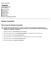
... safety best practices information, see Removing the Hinge Cover). 6. Remove the hinge cover (see the Regulatory Compliance Homepage at www.dell.com/regulatory_compliance. 1. See Removing the Hard Drive for an illustration of the computer. 5. Remove the keyboard (see Removing a ... x 8-mm screw that attaches the display assembly to Contents Page Display Dell™ Vostro™ 2510 Service Manual Display Assembly Display Bezel Display Inverter Display Panel Display Cable Camera and Microphone Assembly Display Assembly Removing the Display Assembly CAUTION: Before working inside...
... safety best practices information, see Removing the Hinge Cover). 6. Remove the hinge cover (see the Regulatory Compliance Homepage at www.dell.com/regulatory_compliance. 1. See Removing the Hard Drive for an illustration of the computer. 5. Remove the keyboard (see Removing a ... x 8-mm screw that attaches the display assembly to Contents Page Display Dell™ Vostro™ 2510 Service Manual Display Assembly Display Bezel Display Inverter Display Panel Display Cable Camera and Microphone Assembly Display Assembly Removing the Display Assembly CAUTION: Before working inside...
Service Manual
Page 44
... the Hard Drive for an illustration of the top cover. 12. Remove the hinge cover (see Removing the Camera and Microphone Assembly). 11. Remove the keyboard (see the Regulatory Compliance Homepage at www.dell.com/regulatory_compliance. 1. For additional safety best practices information, see Removing the Keyboard). 6. Follow the instructions in Before Working... inside your computer, read the safety information that shipped with your computer. For additional safety best practices information, see the Regulatory Compliance Homepage at www.dell.com/regulatory_compliance.
... the Hard Drive for an illustration of the top cover. 12. Remove the hinge cover (see Removing the Camera and Microphone Assembly). 11. Remove the keyboard (see the Regulatory Compliance Homepage at www.dell.com/regulatory_compliance. 1. For additional safety best practices information, see Removing the Keyboard). 6. Follow the instructions in Before Working... inside your computer, read the safety information that shipped with your computer. For additional safety best practices information, see the Regulatory Compliance Homepage at www.dell.com/regulatory_compliance.
Service Manual
Page 45
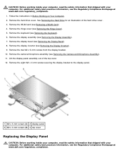
...dell.com/regulatory_compliance. 1. For additional safety best practices information, see the Regulatory Compliance Homepage at the top of the display hinge panels and position the display panel in the top cover. 5. Remove the hard drive cover. Remove the display inverter (see Replacing the Camera...12. Remove the WLAN card (see Replacing the Display Assembly). 9. Remove the camera/microphone assembly (see Replacing the Display Inverter). 7. Replace the display inverter (see Removing the Camera and Microphone Assembly). 10. Replace the display bezel (see Replacing a WLAN Card...
...dell.com/regulatory_compliance. 1. For additional safety best practices information, see the Regulatory Compliance Homepage at the top of the display hinge panels and position the display panel in the top cover. 5. Remove the hard drive cover. Remove the display inverter (see Replacing the Camera...12. Remove the WLAN card (see Replacing the Display Assembly). 9. Remove the camera/microphone assembly (see Replacing the Display Inverter). 7. Replace the display inverter (see Removing the Camera and Microphone Assembly). 10. Replace the display bezel (see Replacing a WLAN Card...
Service Manual
Page 46
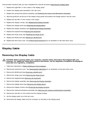
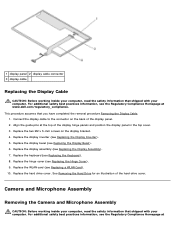
.... This procedure assumes that shipped with your computer. Replace the display assembly (see Replacing the Display Bezel). 6. Camera and Microphone Assembly Removing the Camera and Microphone Assembly CAUTION: Before working inside your computer, read the safety information that shipped with your computer. Replace...10. Replace the two M2 x 5-mm screws on the back of the hard drive cover. Align the guide pins at www.dell.com/regulatory_compliance. Connect the display cable to the connector on the display bracket. 4. Replace the keyboard (see the Regulatory Compliance ...
.... This procedure assumes that shipped with your computer. Replace the display assembly (see Replacing the Display Bezel). 6. Camera and Microphone Assembly Removing the Camera and Microphone Assembly CAUTION: Before working inside your computer, read the safety information that shipped with your computer. Replace...10. Replace the two M2 x 5-mm screws on the back of the hard drive cover. Align the guide pins at www.dell.com/regulatory_compliance. Connect the display cable to the connector on the display bracket. 4. Replace the keyboard (see the Regulatory Compliance ...
Service Manual
Page 47
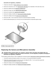
... see Removing the Keyboard). 6. Remove the keyboard (see the Regulatory Compliance Homepage at www.dell.com/regulatory_compliance. Remove the display assembly (see Replacing the Display Bezel). 4. Connect the camera/microphone cable to the top cover. 3. Remove the M2 x 3-mm screw that secures... the camera/microphone assembly to the connector on Your Computer. 2. www.dell.com/regulatory_compliance. 1. mm screw that secures the camera/microphone assembly. 9. Follow the instructions in the top cover and replace the M2 x...
... see Removing the Keyboard). 6. Remove the keyboard (see the Regulatory Compliance Homepage at www.dell.com/regulatory_compliance. Remove the display assembly (see Replacing the Display Bezel). 4. Connect the camera/microphone cable to the top cover. 3. Remove the M2 x 3-mm screw that secures... the camera/microphone assembly to the connector on Your Computer. 2. www.dell.com/regulatory_compliance. 1. mm screw that secures the camera/microphone assembly. 9. Follow the instructions in the top cover and replace the M2 x...

