Setup and Quick Reference Guide
Page 4
3 Specifications 23 4 Troubleshooting 35 Tools 35 Power Lights 35 Beep Codes 35 Error Messages 37 Dell Diagnostics 42 Solving Problems 44 Power Problems 45 Memory Problems 46 Lockups and Software Problems 47 Dell™ Technical Update Service 49 Dell Support Utility 49 5 Reinstalling Software 51 Drivers 51 Identifying Drivers 51 Reinstalling Drivers and Utilities 51 Restoring Your Operating System 54 Using Microsoft Windows System Restore . . . . . 54 Using Dell™ PC Restore and Dell Factory Image Restore 56 Using the Operating System Media 59 4 Contents
3 Specifications 23 4 Troubleshooting 35 Tools 35 Power Lights 35 Beep Codes 35 Error Messages 37 Dell Diagnostics 42 Solving Problems 44 Power Problems 45 Memory Problems 46 Lockups and Software Problems 47 Dell™ Technical Update Service 49 Dell Support Utility 49 5 Reinstalling Software 51 Drivers 51 Identifying Drivers 51 Reinstalling Drivers and Utilities 51 Restoring Your Operating System 54 Using Microsoft Windows System Restore . . . . . 54 Using Dell™ PC Restore and Dell Factory Image Restore 56 Using the Operating System Media 59 4 Contents

Setup and Quick Reference Guide
Page 24
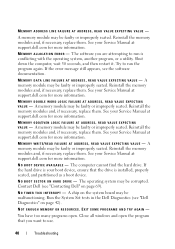
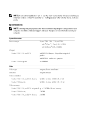
...-Picture Card • Hi Speed-SD • Hi Density-SD Memory Memory module connector 2 DIMM slots Memory module capacity 512 MB, 1 GB, or 2 GB Memory type DDR2 667 MHz Minimum memory 512 MB Maximum memory 4 GB NOTE: In order to take advantage of the dual-channel... bandwidth capability, both USB- NOTE: The available memory displayed does not reflect the complete maximum memory installed because some memory is reserved for system files. 24 Specifications ExpressCard (continued) ExpressCard connector Cards supported ExpressCard ...
...-Picture Card • Hi Speed-SD • Hi Density-SD Memory Memory module connector 2 DIMM slots Memory module capacity 512 MB, 1 GB, or 2 GB Memory type DDR2 667 MHz Minimum memory 512 MB Maximum memory 4 GB NOTE: In order to take advantage of the dual-channel... bandwidth capability, both USB- NOTE: The available memory displayed does not reflect the complete maximum memory installed because some memory is reserved for system files. 24 Specifications ExpressCard (continued) ExpressCard connector Cards supported ExpressCard ...

Setup and Quick Reference Guide
Page 26
... and 1510 discrete: • NVIDIA GeForce 8400M GS, 64 bit Vostro 1710 discrete: • NVIDIA GeForce 8600M GS, 128 bit Vostro 1310, 1510, and 1710 integrated: • up to 256 MB of shared memory Vostro 1310 discrete: • 128 MB Vostro 1510 discrete: • 256 MB Vostro 1710 discrete: • 256 MB LVDS high-definition audio (HDA) Realtek ALC268...
... and 1510 discrete: • NVIDIA GeForce 8400M GS, 64 bit Vostro 1710 discrete: • NVIDIA GeForce 8600M GS, 128 bit Vostro 1310, 1510, and 1710 integrated: • up to 256 MB of shared memory Vostro 1310 discrete: • 128 MB Vostro 1510 discrete: • 256 MB Vostro 1710 discrete: • 256 MB LVDS high-definition audio (HDA) Realtek ALC268...
Setup and Quick Reference Guide
Page 35
If the power light is blinking amber, the computer is receiving electrical power, a device such as a memory module or graphics card might emit a series of beeps during start-up if the monitor cannot display errors or problems. This series of beeps, called a ...
If the power light is blinking amber, the computer is receiving electrical power, a device such as a memory module or graphics card might emit a series of beeps during start-up if the monitor cannot display errors or problems. This series of beeps, called a ...

Setup and Quick Reference Guide
Page 36
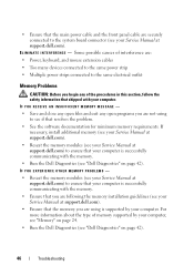
... additional module. board failure 4 RAM Read/Write 1 Ensure that no special memory failure module/memory connector placement requirements exist (see your Service Manual at support.dell.com). 2 Verify that the memory modules that you are installing are detected installed, remove the modules, reinstall one... beeps during start-up: 1 Write down the beep code. 2 Run the Dell Diagnostics to identify a more memory modules are compatible with your computer (see your Service Manual at support.dell.com), and then restart the computer. Continue until you have identified a faulty...
... additional module. board failure 4 RAM Read/Write 1 Ensure that no special memory failure module/memory connector placement requirements exist (see your Service Manual at support.dell.com). 2 Verify that the memory modules that you are installing are detected installed, remove the modules, reinstall one... beeps during start-up: 1 Write down the beep code. 2 Run the Dell Diagnostics to identify a more memory modules are compatible with your computer (see your Service Manual at support.dell.com), and then restart the computer. Continue until you have identified a faulty...

Setup and Quick Reference Guide
Page 37
... or more information. Reinstall the memory modules and, if necessary, replace them. Troubleshooting 37 For an external mouse, check the cable connection. If the problem persists, contact Dell (see "Dell Diagnostics" on page 42). DATA... that shipped with your Service Manual failure. C D D R I V E C O N T R O L L E R F A I L U R E - The touch pad or external mouse may be faulty. Contact Dell (see the documentation for more memory modules may be faulty or improperly seated. Possible at support.dell.com). motherboard failure. 6 Video BIOS Test Contact...
... or more information. Reinstall the memory modules and, if necessary, replace them. Troubleshooting 37 For an external mouse, check the cable connection. If the problem persists, contact Dell (see "Dell Diagnostics" on page 42). DATA... that shipped with your Service Manual failure. C D D R I V E C O N T R O L L E R F A I L U R E - The touch pad or external mouse may be faulty. Contact Dell (see the documentation for more memory modules may be faulty or improperly seated. Possible at support.dell.com). motherboard failure. 6 Video BIOS Test Contact...
Setup and Quick Reference Guide
Page 38
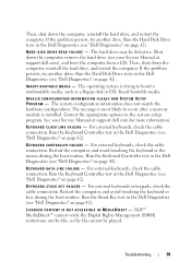
.... D I S K D R I V E C O N F I G U R A T I V E - The amount of paper. If the error appears again, contact Dell (see your Service Manual at support.dell.com for example, Printer out of memory recorded in nonvolatile memory (NVRAM) does not match the memory installed in the Dell Diagnostics (see your Service Manual at support.dell.com), and boot the computer from a CD. T H E F I L E B E I N G C O P I E D I S T O O L A R G E F O R T H E D E S T I N A T I O N D R I O N E R R O R - The file that...
.... D I S K D R I V E C O N F I G U R A T I V E - The amount of paper. If the error appears again, contact Dell (see your Service Manual at support.dell.com for example, Printer out of memory recorded in nonvolatile memory (NVRAM) does not match the memory installed in the Dell Diagnostics (see your Service Manual at support.dell.com), and boot the computer from a CD. T H E F I L E B E I N G C O P I E D I S T O O L A R G E F O R T H E D E S T I N A T I O N D R I O N E R R O R - The file that...
Setup and Quick Reference Guide
Page 39
...O N T R O L L E R F A I L U R E - K E Y B O A R D D A T A L I N E F A I L U R E - Run the Keyboard Controller test in the Dell Diagnostics (see "Dell Diagnostics" on the file, so the file cannot be defective. The hard drive may be played. INSERT BOOTABLE MEDIA - D I S K D R I V E R E A D F A I L U R E - The message is most likely... to occur after a memory module is trying to boot to nonbootable media, such as a floppy disk or CD. Dell™ MediaDirect™ cannot verify the Digital Rights Management (DRM) restrictions on page 42). ...
...O N T R O L L E R F A I L U R E - K E Y B O A R D D A T A L I N E F A I L U R E - Run the Keyboard Controller test in the Dell Diagnostics (see "Dell Diagnostics" on the file, so the file cannot be defective. The hard drive may be played. INSERT BOOTABLE MEDIA - D I S K D R I V E R E A D F A I L U R E - The message is most likely... to occur after a memory module is trying to boot to nonbootable media, such as a floppy disk or CD. Dell™ MediaDirect™ cannot verify the Digital Rights Management (DRM) restrictions on page 42). ...
Setup and Quick Reference Guide
Page 40
... you want to use. 40 Troubleshooting Shut down the computer, wait 30 seconds, and then restart it. A memory module may be faulty or improperly seated. N O B O O T D E V I C E A V A I N T E R R U P T - If the hard drive is your Service Manual at support.dell.com for more information. N O T I M E R T I C K I L A B L E - Close all windows and open . See your boot device, ensure that you...
... you want to use. 40 Troubleshooting Shut down the computer, wait 30 seconds, and then restart it. A memory module may be faulty or improperly seated. N O B O O T D E V I C E A V A I N T E R R U P T - If the hard drive is your Service Manual at support.dell.com for more information. N O T I M E R T I C K I L A B L E - Close all windows and open . See your boot device, ensure that you...

Setup and Quick Reference Guide
Page 42
...Set tests in the system setup program does not match the system clock. Connect your Service Manual at support.dell.com). TIME- The keyboard controller may be malfunctioning, or a memory module may be malfunctioning. Insert a disk into the drive and try to an electrical outlet; OF - ...TI M E - Run the System Memory tests and the Keyboard Controller test in Lockups and Software Problems (see "Dell Diagnostics" on page 47) and run the Dell Diagnostics before you experience a problem with your computer. If the problem persists, contact...
...Set tests in the system setup program does not match the system clock. Connect your Service Manual at support.dell.com). TIME- The keyboard controller may be malfunctioning, or a memory module may be malfunctioning. Insert a disk into the drive and try to an electrical outlet; OF - ...TI M E - Run the System Memory tests and the Keyboard Controller test in Lockups and Software Problems (see "Dell Diagnostics" on page 47) and run the Dell Diagnostics before you experience a problem with your computer. If the problem persists, contact...
Setup and Quick Reference Guide
Page 45
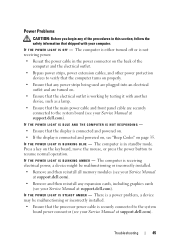
... connected to the system board power connector (see your Service Manual at support.dell.com). I F T H E P O W E R L I G H T I S B L I N K I N G A M B E R - There is a power problem, a device may be malfunctioning or incorrectly installed. • Remove and then reinstall all memory modules (see your Service Manual at support.dell.com). • Remove and then reinstall any expansion cards, including graphics cards...
... connected to the system board power connector (see your Service Manual at support.dell.com). I F T H E P O W E R L I G H T I S B L I N K I N G A M B E R - There is a power problem, a device may be malfunctioning or incorrectly installed. • Remove and then reinstall all memory modules (see your Service Manual at support.dell.com). • Remove and then reinstall any expansion cards, including graphics cards...
Setup and Quick Reference Guide
Page 46
... CAUTION: Before you begin any open programs you are using to the system board connector (see your computer, see "Memory" on page 24. • Run the Dell Diagnostics (see "Dell Diagnostics" on page 42). Some possible causes of interference are: • Power, keyboard, and mouse extension cables • Too many devices connected to...
... CAUTION: Before you begin any open programs you are using to the system board connector (see your computer, see "Memory" on page 24. • Run the Dell Diagnostics (see "Dell Diagnostics" on page 42). Some possible causes of interference are: • Power, keyboard, and mouse extension cables • Too many devices connected to...
Setup and Quick Reference Guide
Page 71
... identifying, 51 reinstalling, 51 Drivers and Utilities media, 52 Dell Diagnostics, 42 E ergonomics information, 62 error messages, 37 beep codes, 35 F Factory Image Restore, 56, 58 Files and Settings Transfer Wizard, 19 H hardware beep codes, 35 Dell Diagnostics, 42 I Internet connection about, 17 options, 17 setting up, 18 M memory troubleshooting, 46 Index 71
... identifying, 51 reinstalling, 51 Drivers and Utilities media, 52 Dell Diagnostics, 42 E ergonomics information, 62 error messages, 37 beep codes, 35 F Factory Image Restore, 56, 58 Files and Settings Transfer Wizard, 19 H hardware beep codes, 35 Dell Diagnostics, 42 I Internet connection about, 17 options, 17 setting up, 18 M memory troubleshooting, 46 Index 71

Setup and Quick Reference Guide
Page 72
..., 62 setup, 15 software reinstalling, 51 troubleshooting, 48 specifications, 23 Starting the Dell Diagnostics From the Drivers and Utilities Media, 44 Starting the Dell Diagnostics From Your Hard Drive, 43 support contacting Dell, 69 System Restore, 54 T Technical Update Service, 49 transferring information to a new... computer, 19 troubleshooting, 35 beep codes, 35 blue screen, 48 computer stops responding, 47 Dell Diagnostics, 42 error messages, 37 lockups, 47 memory, 46 power, 45 power light conditions, 45 power lights, 35 programs and Windows compatibility, 48 restore to previous...
..., 62 setup, 15 software reinstalling, 51 troubleshooting, 48 specifications, 23 Starting the Dell Diagnostics From the Drivers and Utilities Media, 44 Starting the Dell Diagnostics From Your Hard Drive, 43 support contacting Dell, 69 System Restore, 54 T Technical Update Service, 49 transferring information to a new... computer, 19 troubleshooting, 35 beep codes, 35 blue screen, 48 computer stops responding, 47 Dell Diagnostics, 42 error messages, 37 lockups, 47 memory, 46 power, 45 power light conditions, 45 power lights, 35 programs and Windows compatibility, 48 restore to previous...
Setup and Features Information Tech Sheet
Page 8
... is recommended that you turn on system board Data bus integrated video Video controller Vostro 1310, 1510, and 2510 discrete NVIDIA GeForce 8400M GS, 64 bit Vostro 1710 discrete NVIDIA GeForce 8600M GS, 128 bit Video memory Vostro 1310, 1510, and 1710 integrated up to 256 MB of your computer, click Start→ Help and Support...
... is recommended that you turn on system board Data bus integrated video Video controller Vostro 1310, 1510, and 2510 discrete NVIDIA GeForce 8400M GS, 64 bit Vostro 1710 discrete NVIDIA GeForce 8600M GS, 128 bit Video memory Vostro 1310, 1510, and 1710 integrated up to 256 MB of your computer, click Start→ Help and Support...

Service Manual
Page 1
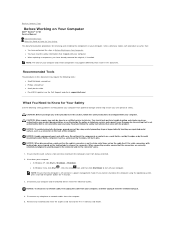
...this document is subject to change without the written permission of Dell Inc.; disclaims any manner whatsoever without notice. © 2008 Dell Inc. A01 Dell Inc. September 2009 Rev. Dell™ Vostro™ 1710 Service Manual Troubleshooting Before Working on Your Computer Hard Drive ...Wireless Local Area Network (WLAN) Card Fan Processor Thermal-Cooling Assembly Processor Module Memory Hinge Cover Keyboard Power ...
...this document is subject to change without the written permission of Dell Inc.; disclaims any manner whatsoever without notice. © 2008 Dell Inc. A01 Dell Inc. September 2009 Rev. Dell™ Vostro™ 1710 Service Manual Troubleshooting Before Working on Your Computer Hard Drive ...Wireless Local Area Network (WLAN) Card Fan Processor Thermal-Cooling Assembly Processor Module Memory Hinge Cover Keyboard Power ...
Service Manual
Page 2
...your computer. Disconnect any installed cards from the computer. 5. Remove any telephone or network cables from the ExpressCard slot and the 8-in-1 memory card reader. l When replacing a component, you cannot shut down your computer. CAUTION: Before you begin any of the procedures in this... computer. Do not touch the components or contacts on a card. Back to Contents Page Before Working on Your Computer Dell™ Vostro™ 1710 Service Manual Recommended Tools What You Need to Know for Your Safety This document provides procedures for removing and installing the components...
...your computer. Disconnect any installed cards from the computer. 5. Remove any telephone or network cables from the ExpressCard slot and the 8-in-1 memory card reader. l When replacing a component, you cannot shut down your computer. CAUTION: Before you begin any of the procedures in this... computer. Do not touch the components or contacts on a card. Back to Contents Page Before Working on Your Computer Dell™ Vostro™ 1710 Service Manual Recommended Tools What You Need to Know for Your Safety This document provides procedures for removing and installing the components...
Service Manual
Page 9
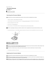
...the ZIF socket. NOTICE: Ensure that the cam lock is perpendicular to the processor when turning the cam screw. 6. Remove the memory cover and set it is in an intermittent connection or permanent damage To loosen the ZIF socket, use a small, flat-blade ...safety instructions that shipped with your computer. 1. NOTICE: Do not touch the processor die. Back to Contents Page Processor Module Dell™ Vostro™ 1710 Service Manual Removing the Processor Module Replacing the Processor Module Removing the Processor Module CAUTION: Before you begin the following procedure, ...
...the ZIF socket. NOTICE: Ensure that the cam lock is perpendicular to the processor when turning the cam screw. 6. Remove the memory cover and set it is in an intermittent connection or permanent damage To loosen the ZIF socket, use a small, flat-blade ...safety instructions that shipped with your computer. 1. NOTICE: Do not touch the processor die. Back to Contents Page Processor Module Dell™ Vostro™ 1710 Service Manual Removing the Processor Module Replacing the Processor Module Removing the Processor Module CAUTION: Before you begin the following procedure, ...

Service Manual
Page 10
Replace the fan (see Replacing the Processor Thermal-Cooling Assembly). 4. Replace the processor thermal-cooling assembly (see Replacing the Fan). 5. Replace the memory cover and tighten the eight screws that you will receive a new thermal pad along with the pin-1 corner of the processor module with a tech sheet ... a triangle that aligns with the triangle on the pin-1 corner of the module are aligned at the same height. This procedure assumes that secure the memory cover.
Replace the fan (see Replacing the Processor Thermal-Cooling Assembly). 4. Replace the processor thermal-cooling assembly (see Replacing the Fan). 5. Replace the memory cover and tighten the eight screws that you will receive a new thermal pad along with the pin-1 corner of the processor module with a tech sheet ... a triangle that aligns with the triangle on the pin-1 corner of the module are aligned at the same height. This procedure assumes that secure the memory cover.
Service Manual
Page 11
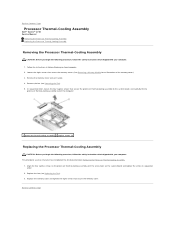
... to the system board, and carefully lift the processor thermal-cooling assembly out of the memory cover.) 3. This procedure assumes that secure the memory cover. (See Removing a Memory Module for an illustration of the computer. 1 processor thermal-cooling assembly 2 captive screws... the removal procedure Removing the Processor Thermal-Cooling Assembly. 1. Back to Contents Page Processor Thermal-Cooling Assembly Dell™ Vostro™ 1710 Service Manual Removing the Processor Thermal-Cooling Assembly Replacing the Processor Thermal-Cooling Assembly Removing the Processor Thermal-Cooling...
... to the system board, and carefully lift the processor thermal-cooling assembly out of the memory cover.) 3. This procedure assumes that secure the memory cover. (See Removing a Memory Module for an illustration of the computer. 1 processor thermal-cooling assembly 2 captive screws... the removal procedure Removing the Processor Thermal-Cooling Assembly. 1. Back to Contents Page Processor Thermal-Cooling Assembly Dell™ Vostro™ 1710 Service Manual Removing the Processor Thermal-Cooling Assembly Replacing the Processor Thermal-Cooling Assembly Removing the Processor Thermal-Cooling...


