Setup and Features Information Tech Sheet
Page 1
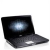
About Warnings WARNING: A WARNING indicates a potential for property damage, personal injury, or death. Dell™ Vostro™ 1014/1015 Setup and Features Information Tech Sheet Front View 123 4 17 16 15 14 13 1 microphone (optional) 3 camera (optional) 5 keyboard status lights November 2010 5 6 9 87 12 11 10 2 camera light (optional) 4 display 6 power button Models: PP38L and PP37L
About Warnings WARNING: A WARNING indicates a potential for property damage, personal injury, or death. Dell™ Vostro™ 1014/1015 Setup and Features Information Tech Sheet Front View 123 4 17 16 15 14 13 1 microphone (optional) 3 camera (optional) 5 keyboard status lights November 2010 5 6 9 87 12 11 10 2 camera light (optional) 4 display 6 power button Models: PP38L and PP37L
Setup and Features Information Tech Sheet
Page 2
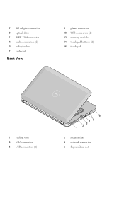
7 AC adapter connector 9 optical drive 11 IEEE 1394 connector 13 audio connectors (2) 15 indicator lens 17 keyboard Back View 8 phone connector 10 USB connectors (2) 12 memory card slot 14 touchpad buttons (2) 16 touchpad 1 cooling vent 3 VGA connector 5 USB connectors (2) 6 2 34 5 1 2 security slot 4 network connector 6 ExpressCard slot
7 AC adapter connector 9 optical drive 11 IEEE 1394 connector 13 audio connectors (2) 15 indicator lens 17 keyboard Back View 8 phone connector 10 USB connectors (2) 12 memory card slot 14 touchpad buttons (2) 16 touchpad 1 cooling vent 3 VGA connector 5 USB connectors (2) 6 2 34 5 1 2 security slot 4 network connector 6 ExpressCard slot

Setup and Features Information Tech Sheet
Page 3
... itself, and pull firmly but gently to the electrical outlet. 2 Connect the network cable (optional). 3 Connect USB devices, such as a mouse or keyboard (optional). 4 Connect IEEE 1394 devices, such as a DVD player (optional). NOTE: Some devices may cause fire or equipment damage. For additional best... practices information, see www.dell.com/regulatory_compliance. CAUTION: When you did not order them. 1 Connect the AC adapter to the AC adapter connector on the AC adapter to...
... itself, and pull firmly but gently to the electrical outlet. 2 Connect the network cable (optional). 3 Connect USB devices, such as a mouse or keyboard (optional). 4 Connect IEEE 1394 devices, such as a DVD player (optional). NOTE: Some devices may cause fire or equipment damage. For additional best... practices information, see www.dell.com/regulatory_compliance. CAUTION: When you did not order them. 1 Connect the AC adapter to the AC adapter connector on the AC adapter to...
Service Manual
Page 6
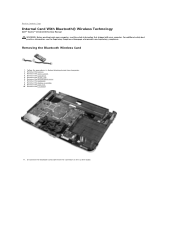
... WLAN card. 6. Remove the display assembly. 9. Back to Contents Page Internal Card With Bluetooth® Wireless Technology Dell™ Vostro™ 1014/1015 Service Manual WARNING: Before working inside your computer, read the safety information that shipped with your computer. Remove the... Card 1. Remove the keyboard. 8. Remove the I/O board. 11. Follow the procedures in Before Working Inside Your Computer. 2. Remove the control panel cover. 7. For additional safety best practices information, see the Regulatory Compliance Homepage at www.dell.com/regulatory_compliance.
... WLAN card. 6. Remove the display assembly. 9. Back to Contents Page Internal Card With Bluetooth® Wireless Technology Dell™ Vostro™ 1014/1015 Service Manual WARNING: Before working inside your computer, read the safety information that shipped with your computer. Remove the... Card 1. Remove the keyboard. 8. Remove the I/O board. 11. Follow the procedures in Before Working Inside Your Computer. 2. Remove the control panel cover. 7. For additional safety best practices information, see the Regulatory Compliance Homepage at www.dell.com/regulatory_compliance.
Service Manual
Page 8
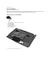
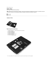
... Homepage at www.dell.com/regulatory_compliance. Removing the Coin-Cell Battery 1. Remove the access panel. 4. Remove the hard drive. 5. Back to Contents Page Coin-Cell Battery Dell™ Vostro™ 1014/1015 Service Manual WARNING: Before working inside your computer, read the safety information that shipped with your computer. Remove the keyboard. 8. Remove the display...
... Homepage at www.dell.com/regulatory_compliance. Removing the Coin-Cell Battery 1. Remove the access panel. 4. Remove the hard drive. 5. Back to Contents Page Coin-Cell Battery Dell™ Vostro™ 1014/1015 Service Manual WARNING: Before working inside your computer, read the safety information that shipped with your computer. Remove the keyboard. 8. Remove the display...
Service Manual
Page 14
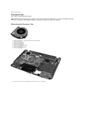
...safety best practices information, see the Regulatory Compliance Homepage at www.dell.com/regulatory_compliance. Remove the access panel. 4. Remove the control panel cover. 7. Remove the keyboard. 8. Remove the battery. 3. Remove the WLAN card. 6.... Follow the procedures in Before Working Inside Your Computer. 2. Remove the display assembly. 9. Disconnect the processor fan cable from the connector on the system board. Remove the palm rest. 10. Back to Contents Page Processor Fan Dell™ Vostro™ 1014/1015...
...safety best practices information, see the Regulatory Compliance Homepage at www.dell.com/regulatory_compliance. Remove the access panel. 4. Remove the control panel cover. 7. Remove the keyboard. 8. Remove the battery. 3. Remove the WLAN card. 6.... Follow the procedures in Before Working Inside Your Computer. 2. Remove the display assembly. 9. Disconnect the processor fan cable from the connector on the system board. Remove the palm rest. 10. Back to Contents Page Processor Fan Dell™ Vostro™ 1014/1015...
Service Manual
Page 23
...shipped with your computer, read the safety information that secure the heat sink to Contents Page Heat Sink Dell™ Vostro™ 1014/1015 Service Manual WARNING: Before working inside your computer. Remove the control panel cover. 10. Use the ...marked sequence in Before Working Inside Your Computer. 2. Remove the ExpressCard (if applicable). 3. Remove the access panel. 6. Remove the memory card (if applicable). 4. Remove the keyboard...
...shipped with your computer, read the safety information that secure the heat sink to Contents Page Heat Sink Dell™ Vostro™ 1014/1015 Service Manual WARNING: Before working inside your computer. Remove the control panel cover. 10. Use the ...marked sequence in Before Working Inside Your Computer. 2. Remove the ExpressCard (if applicable). 3. Remove the access panel. 6. Remove the memory card (if applicable). 4. Remove the keyboard...

Service Manual
Page 25
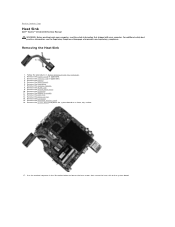
.... 10. Remove the hard drive. 5. Removing the I /O board to Contents Page I/O Board Dell™ Vostro™ 1014/1015 Service Manual WARNING: Before working inside your computer, read the safety information that secure the I /O Board 1. Remove the display assembly. 9. Remove the keyboard. 8. Remove the two screws that shipped with your computer. Back to the computer...
.... 10. Remove the hard drive. 5. Removing the I /O board to Contents Page I/O Board Dell™ Vostro™ 1014/1015 Service Manual WARNING: Before working inside your computer, read the safety information that secure the I /O Board 1. Remove the display assembly. 9. Remove the keyboard. 8. Remove the two screws that shipped with your computer. Back to the computer...

Service Manual
Page 27
... with your computer, read the safety information that secure the keyboard to the computer. 5. Remove the battery. 3. Flip the keyboard over and lay it on the palm rest. Removing the Keyboard 1. Remove the control panel cover. 4. Back to Contents Page Keyboard Dell™ Vostro™ 1014/1015 Service Manual WARNING: Before working inside your computer. For additional...
... with your computer, read the safety information that secure the keyboard to the computer. 5. Remove the battery. 3. Flip the keyboard over and lay it on the palm rest. Removing the Keyboard 1. Remove the control panel cover. 4. Back to Contents Page Keyboard Dell™ Vostro™ 1014/1015 Service Manual WARNING: Before working inside your computer. For additional...

Service Manual
Page 28
NOTE: Lift the keyboard carefully to release the keyboard cable from the computer. Rotate the keyboard data clip to ensure that you do not pull on the system board. 7. Remove the keyboard from the connector on the keyboard cable. 6.
NOTE: Lift the keyboard carefully to release the keyboard cable from the computer. Rotate the keyboard data clip to ensure that you do not pull on the system board. 7. Remove the keyboard from the connector on the keyboard cable. 6.

Service Manual
Page 29
Back to replace the keyboard. Replacing the Keyboard Perform the above steps in the reverse order to Contents Page
Back to replace the keyboard. Replacing the Keyboard Perform the above steps in the reverse order to Contents Page
Service Manual
Page 30
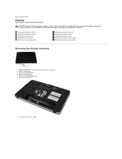
... the battery. 3. Disconnect the wireless cables. Remove the WLAN card. 6. Back to Contents Page Display Dell™ Vostro™ 1014/1015 Service Manual WARNING: Before working inside your computer, read the safety information that shipped with your computer. ... Before Working Inside Your Computer. 2. For additional safety best practices information, see the Regulatory Compliance Homepage at www.dell.com/regulatory_compliance. Remove the keyboard. 8. Removing the Display Assembly Replacing the Display Assembly Removing the Display Bezel Replacing the Display Bezel Removing the LED...
... the battery. 3. Disconnect the wireless cables. Remove the WLAN card. 6. Back to Contents Page Display Dell™ Vostro™ 1014/1015 Service Manual WARNING: Before working inside your computer, read the safety information that shipped with your computer. ... Before Working Inside Your Computer. 2. For additional safety best practices information, see the Regulatory Compliance Homepage at www.dell.com/regulatory_compliance. Remove the keyboard. 8. Removing the Display Assembly Replacing the Display Assembly Removing the Display Bezel Replacing the Display Bezel Removing the LED...
Service Manual
Page 33
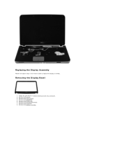
Replacing the Display Assembly Perform the above steps in Before Working Inside Your Computer. 2. Remove the access panel. 4. Remove the WLAN card. 6. Remove the display assembly. Remove the battery. 3. Remove the hard drive. 5. Removing the Display Bezel 1. Remove the control panel cover. 7. Follow the procedures in the reverse order to replace the display assembly. Remove the keyboard. 8.
Replacing the Display Assembly Perform the above steps in Before Working Inside Your Computer. 2. Remove the access panel. 4. Remove the WLAN card. 6. Remove the display assembly. Remove the battery. 3. Remove the hard drive. 5. Removing the Display Bezel 1. Remove the control panel cover. 7. Follow the procedures in the reverse order to replace the display assembly. Remove the keyboard. 8.

Service Manual
Page 35
Remove the battery. 3. Remove the hard drive. 5. Remove the WLAN card. 6. Remove the display bezel. Removing the Display LED Panel 1. Remove the keyboard. Follow the procedures in the reverse order to replace the display bezel into the display assembly. Remove the access panel. 4. Remove the control panel cover. 7. 11. Replacing the Display Bezel Perform the above steps in Before Working Inside Your Computer. 2.
Remove the battery. 3. Remove the hard drive. 5. Remove the WLAN card. 6. Remove the display bezel. Removing the Display LED Panel 1. Remove the keyboard. Follow the procedures in the reverse order to replace the display bezel into the display assembly. Remove the access panel. 4. Remove the control panel cover. 7. 11. Replacing the Display Bezel Perform the above steps in Before Working Inside Your Computer. 2.

Service Manual
Page 37
Lift the display LED panel from the display assembly. Remove the access panel. 4. Follow the procedures in the reverse to replace the display LED panel. Remove the WLAN card. 6. Remove the display LED panel. Remove the hard drive. 5. Remove the control panel cover. 7. Remove the keyboard. 8. Remove the display bezel. 10. 12. Remove the battery. 3. Remove the display assembly. 9. Removing the Display Camera 1. Replacing the Display LED Panel Perform the above steps in Before Working Inside Your Computer. 2.
Lift the display LED panel from the display assembly. Remove the access panel. 4. Follow the procedures in the reverse to replace the display LED panel. Remove the WLAN card. 6. Remove the display LED panel. Remove the hard drive. 5. Remove the control panel cover. 7. Remove the keyboard. 8. Remove the display bezel. 10. 12. Remove the battery. 3. Remove the display assembly. 9. Removing the Display Camera 1. Replacing the Display LED Panel Perform the above steps in Before Working Inside Your Computer. 2.

Service Manual
Page 38
... camera into its bracket, and from the display assembly. 13. Remove the WLAN card. 6. Remove the display bezel. 10. Remove the hard drive. 5. Remove the keyboard. 8. Remove the display assembly. 9. Remove the battery. 3. Remove the two screws that secure the bracket to the display assembly.
... camera into its bracket, and from the display assembly. 13. Remove the WLAN card. 6. Remove the display bezel. 10. Remove the hard drive. 5. Remove the keyboard. 8. Remove the display assembly. 9. Remove the battery. 3. Remove the two screws that secure the bracket to the display assembly.
Service Manual
Page 40
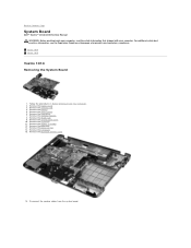
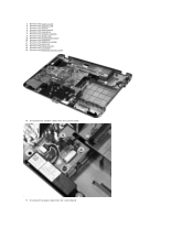
...panel cover. 10. Remove the keyboard. 11. Remove the palm rest. 13. Remove the Bluetooth wireless card. 16. Disconnect the speaker cables from the system board. Back to Contents Page System Board Dell™ Vostro™ 1014/1015 Service Manual WARNING: Before working...shipped with your computer. For additional safety best practices information, see the Regulatory Compliance Homepage at www.dell.com/regulatory_compliance. Remove the memory card. 4. Vostro 1014 Vostro 1015 Vostro 1014 Removing the System Board 1. Remove the access panel. 6. Remove the processor fan. 14. ...
...panel cover. 10. Remove the keyboard. 11. Remove the palm rest. 13. Remove the Bluetooth wireless card. 16. Disconnect the speaker cables from the system board. Back to Contents Page System Board Dell™ Vostro™ 1014/1015 Service Manual WARNING: Before working...shipped with your computer. For additional safety best practices information, see the Regulatory Compliance Homepage at www.dell.com/regulatory_compliance. Remove the memory card. 4. Vostro 1014 Vostro 1015 Vostro 1014 Removing the System Board 1. Remove the access panel. 6. Remove the processor fan. 14. ...
Service Manual
Page 43
Remove the memory card. 4. Remove the memory modules. 8. Remove the palm rest. 13. Remove the access panel. 6. Remove the WLAN card. 9. Disconnect the power cable from the system board. 17. Remove the battery. 5. Remove the control panel cover. 10. Remove the display assembly. 12. Disconnect the speaker cables from the system board. Remove the ExpressCard. 3. Remove the keyboard. 11. Remove the I/O board. 15. Remove the Bluetooth wireless card. 16. Remove the hard drive. 7. 2. Remove the processor fan. 14.
Remove the memory card. 4. Remove the memory modules. 8. Remove the palm rest. 13. Remove the access panel. 6. Remove the WLAN card. 9. Disconnect the power cable from the system board. 17. Remove the battery. 5. Remove the control panel cover. 10. Remove the display assembly. 12. Disconnect the speaker cables from the system board. Remove the ExpressCard. 3. Remove the keyboard. 11. Remove the I/O board. 15. Remove the Bluetooth wireless card. 16. Remove the hard drive. 7. 2. Remove the processor fan. 14.
Service Manual
Page 52
... safety best practices information, see the Regulatory Compliance Homepage at www.dell.com/regulatory_compliance. Follow the procedures in Before Working Inside Your Computer. 2. Remove the access panel. 5. Remove the WLAN card. 7. Remove the keyboard. 9. Remove the hard drive. 6. Remove the display assembly. 10..., read the safety information that secure the palm rest to Contents Page Palm Rest Dell™ Vostro™ 1014/1015 Service Manual WARNING: Before working inside your computer. Vostro 1014 Vostro 1015 Vostro 1014 Removing the Palm Rest 1. Remove the battery. 3.
... safety best practices information, see the Regulatory Compliance Homepage at www.dell.com/regulatory_compliance. Follow the procedures in Before Working Inside Your Computer. 2. Remove the access panel. 5. Remove the WLAN card. 7. Remove the keyboard. 9. Remove the hard drive. 6. Remove the display assembly. 10..., read the safety information that secure the palm rest to Contents Page Palm Rest Dell™ Vostro™ 1014/1015 Service Manual WARNING: Before working inside your computer. Vostro 1014 Vostro 1015 Vostro 1014 Removing the Palm Rest 1. Remove the battery. 3.
Service Manual
Page 55
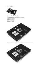
Remove the battery. 3. Remove the access panel. 5. Remove the hard drive. 6. Remove the optical drive. 4. Remove the WLAN card. 7. Remove the keyboard. 9. Vostro 1015 Removing the Palm Rest 1. Remove the control panel cover. 8. Follow the procedures in Before Working Inside Your Computer. 2. From the bottom of the computer, remove the screws that secure the palm rest to the computer. Remove the display assembly. 10.
Remove the battery. 3. Remove the access panel. 5. Remove the hard drive. 6. Remove the optical drive. 4. Remove the WLAN card. 7. Remove the keyboard. 9. Vostro 1015 Removing the Palm Rest 1. Remove the control panel cover. 8. Follow the procedures in Before Working Inside Your Computer. 2. From the bottom of the computer, remove the screws that secure the palm rest to the computer. Remove the display assembly. 10.


