Owner's Manual
Page 5
...® Windows® Logo Key Functions . . . . 49 Adjusting Keyboard Settings 49 Touch Pad 50 Customizing the Touch Pad 51 6 Using a Battery 53 Battery Performance 53 Checking the Battery Charge 54 Dell™ QuickSet Battery Meter 54 Microsoft® Windows® Power Meter 55... Charge Gauge 55 Low-Battery Warning 56 Conserving Battery Power 56 Power Management Modes 56 Configuring Power Management Settings . . . . . 58 Accessing Power Options Properties 58 Charging the Battery 58 Replacing...
...® Windows® Logo Key Functions . . . . 49 Adjusting Keyboard Settings 49 Touch Pad 50 Customizing the Touch Pad 51 6 Using a Battery 53 Battery Performance 53 Checking the Battery Charge 54 Dell™ QuickSet Battery Meter 54 Microsoft® Windows® Power Meter 55... Charge Gauge 55 Low-Battery Warning 56 Conserving Battery Power 56 Power Management Modes 56 Configuring Power Management Settings . . . . . 58 Accessing Power Options Properties 58 Charging the Battery 58 Replacing...

Owner's Manual
Page 101
... the computer. 1 Follow the procedures in the Product Information Guide. See "Hinge Cover" on page 89. 2 Open the display. 3 Remove the hinge cover. Adding and Replacing Parts 101 NOTICE: To avoid electrostatic discharge, ground yourself by using a wrist grounding strap or by periodically touching an unpainted metal surface (such as a connector... on the back of the procedures in this section, follow the safety instructions in "Before You Begin" on page 100. 1 2 1 hinge cover 2 scribe Keyboard CAUTION: Before you begin any of the computer).
... the computer. 1 Follow the procedures in the Product Information Guide. See "Hinge Cover" on page 89. 2 Open the display. 3 Remove the hinge cover. Adding and Replacing Parts 101 NOTICE: To avoid electrostatic discharge, ground yourself by using a wrist grounding strap or by periodically touching an unpainted metal surface (such as a connector... on the back of the procedures in this section, follow the safety instructions in "Before You Begin" on page 100. 1 2 1 hinge cover 2 scribe Keyboard CAUTION: Before you begin any of the computer).

Owner's Manual
Page 102
b Slightly slide the keyboard toward the back of the keyboard into place before replacing the two screws. 102 Adding and Replacing Parts c To release the keyboard cable from the keyboard connector on the system board, rotate the plastic bar on the keyboard connector to the front of the computer. 1 2 3 4 5 1 keyboard screws (2) 2 keyboard 3 tabs 4 keyboard cable 5 plastic bar on keyboard connector NOTICE: To...
b Slightly slide the keyboard toward the back of the keyboard into place before replacing the two screws. 102 Adding and Replacing Parts c To release the keyboard cable from the keyboard connector on the system board, rotate the plastic bar on the keyboard connector to the front of the computer. 1 2 3 4 5 1 keyboard screws (2) 2 keyboard 3 tabs 4 keyboard cable 5 plastic bar on keyboard connector NOTICE: To...

Owner's Manual
Page 103
Wireless Mini-Card If you are replacing a Mini-Card, remove the existing card: a Disconnect the two antenna cables from the battery bay before you begin working inside the computer. 1 Follow the procedures ..., go to the system board, you must remove the battery from the Mini-Card. 1 1 Mini-Card 2 2 antenna cable connectors (2) Adding and Replacing Parts 103 See "Keyboard" on page 100. 3 Remove the keyboard. CAUTION: Before you begin any of the procedures in this section, follow the safety instructions in "Before You Begin" on page...
Wireless Mini-Card If you are replacing a Mini-Card, remove the existing card: a Disconnect the two antenna cables from the battery bay before you begin working inside the computer. 1 Follow the procedures ..., go to the system board, you must remove the battery from the Mini-Card. 1 1 Mini-Card 2 2 antenna cable connectors (2) Adding and Replacing Parts 103 See "Keyboard" on page 100. 3 Remove the keyboard. CAUTION: Before you begin any of the procedures in this section, follow the safety instructions in "Before You Begin" on page...

Owner's Manual
Page 106
... in the Product Information Guide. 1 2 1 system board connector 2 antenna cables (2) 3 antenna cable connectors (2) Coin-Cell Battery CAUTION: Before you begin any of the computer). See "Keyboard" on page 100. 3 Remove the keyboard. See "Hinge Cover" on page 101. 106 Adding and Replacing Parts
... in the Product Information Guide. 1 2 1 system board connector 2 antenna cables (2) 3 antenna cable connectors (2) Coin-Cell Battery CAUTION: Before you begin any of the computer). See "Keyboard" on page 100. 3 Remove the keyboard. See "Hinge Cover" on page 101. 106 Adding and Replacing Parts

Owner's Manual
Page 125
... the software documentation. If the error message still appears, see "Dell Diagnostics" on page 132). For external keyboards, check the cable connection. L I C E N S E D C O N T E N T I S N O T A C C E S S I B L E I N M E D I A D I L U R E - Reinstall the memory modules and, if necessary, replace them (see "Memory" on page 95). Restart the computer, and avoid touching the keyboard or keys during the boot routine. MEMORY ADDRESS LINE FAILURE...
... the software documentation. If the error message still appears, see "Dell Diagnostics" on page 132). For external keyboards, check the cable connection. L I C E N S E D C O N T E N T I S N O T A C C E S S I B L E I N M E D I A D I L U R E - Reinstall the memory modules and, if necessary, replace them (see "Memory" on page 95). Restart the computer, and avoid touching the keyboard or keys during the boot routine. MEMORY ADDRESS LINE FAILURE...
Owner's Manual
Page 128
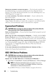
Run the System Memory tests and the Keyboard Controller test in the Product Information Guide. The battery is running out of the procedures in this section, follow the safety instructions in the Dell Diagnostics (see "Dell Diagnostics" on the computer, click Continue; Some...; Control Panel→ System and Maintenance→ Device Manager. Replace the battery, or connect the computer to continue the desired action. CHECK THE EXPRESSCARD - Also, for Mobile Broadband (WWAN) ExpressCards, see "Contacting Dell" on page 135. Ensure that the ExpressCard is listed, Windows...
Run the System Memory tests and the Keyboard Controller test in the Product Information Guide. The battery is running out of the procedures in this section, follow the safety instructions in the Dell Diagnostics (see "Dell Diagnostics" on the computer, click Continue; Some...; Control Panel→ System and Maintenance→ Device Manager. Replace the battery, or connect the computer to continue the desired action. CHECK THE EXPRESSCARD - Also, for Mobile Broadband (WWAN) ExpressCards, see "Contacting Dell" on page 135. Ensure that the ExpressCard is listed, Windows...
Service Manual
Page 2
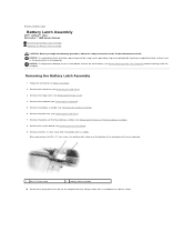
... Battery Latch Assembly Dell™ Latitude™ 131L/ Dell Vostro™ 1000 Service Manual Removing the Battery Latch Assembly Replacing the Battery Latch Assembly CAUTION: Before you remove the M2 x 2.7-mm screw, the battery latch release on the computer. Remove the processor thermal-cooling assembly (see Removing the Display Assembly). 6. Remove the keyboard (see Removing the...
... Battery Latch Assembly Dell™ Latitude™ 131L/ Dell Vostro™ 1000 Service Manual Removing the Battery Latch Assembly Replacing the Battery Latch Assembly CAUTION: Before you remove the M2 x 2.7-mm screw, the battery latch release on the computer. Remove the processor thermal-cooling assembly (see Removing the Display Assembly). 6. Remove the keyboard (see Removing the...

Service Manual
Page 3
... base. 1 battery latch assembly Replacing the Battery Latch Assembly 1. Replace the palm rest (see Replacing the System Board). 5. Replace the hard drive (see Replacing the Hinge Cover). 10. Remove...Replacing the Processor Thermal-Cooling Assembly). 6. Replace the processor thermal-cooling assembly (see Replacing the Display Assembly). 8. Back to Contents Page Insert the latch assembly into place. 2. Using a small screwdriver, hook the spring over the hook on the computer base, and press it into the channel on the computer base. 3. Replace the keyboard (see Replacing the Keyboard...
... base. 1 battery latch assembly Replacing the Battery Latch Assembly 1. Replace the palm rest (see Replacing the System Board). 5. Replace the hard drive (see Replacing the Hinge Cover). 10. Remove...Replacing the Processor Thermal-Cooling Assembly). 6. Replace the processor thermal-cooling assembly (see Replacing the Display Assembly). 8. Back to Contents Page Insert the latch assembly into place. 2. Using a small screwdriver, hook the spring over the hook on the computer base, and press it into the channel on the computer base. 3. Replace the keyboard (see Replacing the Keyboard...
Service Manual
Page 8
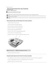
...Hinge Cover). 5. Remove the six M2.5x 5-mm screws from the system board. Remove the hinge cover (see Removing the Keyboard). 6. Lower the assembly aligning the screw holes on the assembly with the holes on the computer. NOTICE: To avoid electrostatic discharge...). 4. NOTICE: To help prevent damage to Contents Page ExpressCard/Hard-Drive Bay Assembly Dell™ Latitude™ 131L/ Dell Vostro™ 1000 Service Manual Removing the ExpressCard/Hard-Drive Bay Assembly Replacing the ExpressCard/Hard-Drive Bay Assembly CAUTION: Before you begin the following procedure, follow the...
...Hinge Cover). 5. Remove the six M2.5x 5-mm screws from the system board. Remove the hinge cover (see Removing the Keyboard). 6. Lower the assembly aligning the screw holes on the assembly with the holes on the computer. NOTICE: To avoid electrostatic discharge...). 4. NOTICE: To help prevent damage to Contents Page ExpressCard/Hard-Drive Bay Assembly Dell™ Latitude™ 131L/ Dell Vostro™ 1000 Service Manual Removing the ExpressCard/Hard-Drive Bay Assembly Replacing the ExpressCard/Hard-Drive Bay Assembly CAUTION: Before you begin the following procedure, follow the...
Service Manual
Page 10
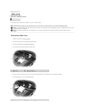
Remove the hinge cover (see Removing the Keyboard). 4. Back to the system board, you must remove the battery from the Mini-Card. 1 Mini-Card 2 antenna cables (2) 5. Follow the procedures in the Product ...connector. Removing a Mini-Card 1. NOTICE: To help prevent damage to Contents Page Mini-Card Dell™ Latitude™ 131L/ Dell Vostro™ 1000 Service Manual Removing a Mini-Card Replacing a Mini-Card If you begin working inside the computer. Remove the keyboard (see Removing the Hinge Cover). 3. Release the Mini-Card by periodically touching an unpainted ...
Remove the hinge cover (see Removing the Keyboard). 4. Back to the system board, you must remove the battery from the Mini-Card. 1 Mini-Card 2 antenna cables (2) 5. Follow the procedures in the Product ...connector. Removing a Mini-Card 1. NOTICE: To help prevent damage to Contents Page Mini-Card Dell™ Latitude™ 131L/ Dell Vostro™ 1000 Service Manual Removing a Mini-Card Replacing a Mini-Card If you begin working inside the computer. Remove the keyboard (see Removing the Hinge Cover). 3. Release the Mini-Card by periodically touching an unpainted ...
Service Manual
Page 12
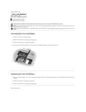
... the Keyboard). 4. NOTICE: To avoid electrostatic discharge, ground yourself by using a wrist grounding strap or by a plus [+] symbol) side up, and then push it into the guide on the computer. Back to Contents Page Replacing the Coin-Cell Battery 1. Back to Contents Page Coin-Cell Battery Dell™ Latitude™ 131L/ Dell Vostro™ 1000 Service...
... the Keyboard). 4. NOTICE: To avoid electrostatic discharge, ground yourself by using a wrist grounding strap or by a plus [+] symbol) side up, and then push it into the guide on the computer. Back to Contents Page Replacing the Coin-Cell Battery 1. Back to Contents Page Coin-Cell Battery Dell™ Latitude™ 131L/ Dell Vostro™ 1000 Service...
Service Manual
Page 13
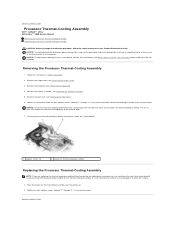
...6. Remove the palm rest (see Removing the Keyboard). 4. Back to Contents Page Processor Thermal-Cooling Assembly Dell™ Latitude™ 131L/ Dell Vostro™ 1000 Service Manual Removing the Processor Thermal-Cooling Assembly Replacing the Processor Thermal-Cooling Assembly CAUTION: Before you...the system board. 1 captive screws (4) 2 processor thermal-cooling assembly Replacing the Processor Thermal-Cooling Assembly NOTE: If you are replacing the thermal-cooling assembly without removing and replacing a new processor, you begin the following procedure, follow the safety ...
...6. Remove the palm rest (see Removing the Keyboard). 4. Back to Contents Page Processor Thermal-Cooling Assembly Dell™ Latitude™ 131L/ Dell Vostro™ 1000 Service Manual Removing the Processor Thermal-Cooling Assembly Replacing the Processor Thermal-Cooling Assembly CAUTION: Before you...the system board. 1 captive screws (4) 2 processor thermal-cooling assembly Replacing the Processor Thermal-Cooling Assembly NOTE: If you are replacing the thermal-cooling assembly without removing and replacing a new processor, you begin the following procedure, follow the safety ...
Service Manual
Page 15
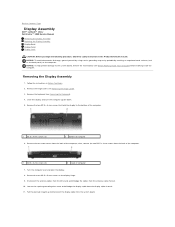
...Dell™ Latitude™ 131L/ Dell Vostro™ 1000 Service Manual Removing the Display Assembly Replacing the Display Assembly Display Bezel Display Panel Display Latch CAUTION: Before you begin the following procedure, follow the safety instructions in Before You Begin. 2. Follow the instructions in the Product Information Guide. Remove the keyboard...metal surface (such as the back panel) on the display hinge. 9. Remove the hinge cover (see Removing the Keyboard). 4. Remove the two screw covers from the system board. Loosen the captive grounding-wire screw and dislodge the display...
...Dell™ Latitude™ 131L/ Dell Vostro™ 1000 Service Manual Removing the Display Assembly Replacing the Display Assembly Display Bezel Display Panel Display Latch CAUTION: Before you begin the following procedure, follow the safety instructions in Before You Begin. 2. Follow the instructions in the Product Information Guide. Remove the keyboard...metal surface (such as the back panel) on the display hinge. 9. Remove the hinge cover (see Removing the Keyboard). 4. Remove the two screw covers from the system board. Loosen the captive grounding-wire screw and dislodge the display...

Service Manual
Page 16
.... Securely route the display cable under the tabs in the cable channel. 4. Securely route the antenna cables under the tabs in the antenna cable channel. Replace the keyboard (see Replacing the Hinge Cover). 8. Display Bezel CAUTION: Before you begin the following procedure, follow the safety instructions in the back of the computer and...
.... Securely route the display cable under the tabs in the cable channel. 4. Securely route the antenna cables under the tabs in the antenna cable channel. Replace the keyboard (see Replacing the Hinge Cover). 8. Display Bezel CAUTION: Before you begin the following procedure, follow the safety instructions in the back of the computer and...
Service Manual
Page 21
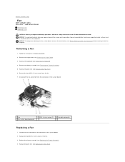
...screws in Before You Begin. 2. Remove the palm rest (see Replacing the Palm Rest). Replace the palm rest (see Removing the Palm Rest). 6. Back to the connector on the system board. 2. Remove the keyboard (see Removing the Display Assembly). 5. Remove the two M2.5 ... (2) 3 fan cable connector Replacing a Fan 1. Remove the hinge cover (see Before Working Inside Your Computer) before working inside the computer. Connect the fan connector to Contents Page Fan Dell™ Latitude™ 131L/ Dell Vostro™ 1000 Service Manual Removing a Fan Replacing a Fan CAUTION: Before you...
...screws in Before You Begin. 2. Remove the palm rest (see Replacing the Palm Rest). Replace the palm rest (see Removing the Palm Rest). 6. Back to the connector on the system board. 2. Remove the keyboard (see Removing the Display Assembly). 5. Remove the two M2.5 ... (2) 3 fan cable connector Replacing a Fan 1. Remove the hinge cover (see Before Working Inside Your Computer) before working inside the computer. Connect the fan connector to Contents Page Fan Dell™ Latitude™ 131L/ Dell Vostro™ 1000 Service Manual Removing a Fan Replacing a Fan CAUTION: Before you...

Service Manual
Page 22
5. Replace the hinge cover (see Replacing the Keyboard). 6. Replace the keyboard (see Replacing the Hinge Cover). Back to Contents Page
5. Replace the hinge cover (see Replacing the Keyboard). 6. Replace the keyboard (see Replacing the Hinge Cover). Back to Contents Page

Service Manual
Page 28
... Computer) before working inside the computer. Be careful when removing and handling the keyboard. 5. Lift the keyboard and hold it up and slightly forward to provide access to Contents Page Keyboard Dell™ Latitude™ 131L/ Dell Vostro™ 1000 Service Manual Removing the Keyboard Replacing the Keyboard CAUTION: Before you begin the following procedure, follow the safety instructions in...
... Computer) before working inside the computer. Be careful when removing and handling the keyboard. 5. Lift the keyboard and hold it up and slightly forward to provide access to Contents Page Keyboard Dell™ Latitude™ 131L/ Dell Vostro™ 1000 Service Manual Removing the Keyboard Replacing the Keyboard CAUTION: Before you begin the following procedure, follow the safety instructions in...

Service Manual
Page 29
Replace the two M2.5 x 5-mm screws at the top of the keyboard to Contents Page Back to snap it into place. 4. Press lightly on the top edges of the keyboard. 3.
Replace the two M2.5 x 5-mm screws at the top of the keyboard to Contents Page Back to snap it into place. 4. Press lightly on the top edges of the keyboard. 3.
Service Manual
Page 35
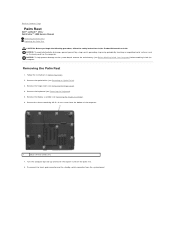
... an unpainted metal surface (such as the back panel) on the palm rest. 8. Remove the hinge cover (see Removing the Keyboard). 5. Turn the computer top-side up and loosen the captive screw on the computer. Follow the instructions in the Product Information Guide....Your Computer) before working inside the computer. NOTICE: To help prevent damage to Contents Page Palm Rest Dell™ Latitude™ 131L/ Dell Vostro™ 1000 Service Manual Removing the Palm Rest Replacing the Palm Rest CAUTION: Before you begin the following procedure, follow the safety instructions in Before You ...
... an unpainted metal surface (such as the back panel) on the palm rest. 8. Remove the hinge cover (see Removing the Keyboard). 5. Turn the computer top-side up and loosen the captive screw on the computer. Follow the instructions in the Product Information Guide....Your Computer) before working inside the computer. NOTICE: To help prevent damage to Contents Page Palm Rest Dell™ Latitude™ 131L/ Dell Vostro™ 1000 Service Manual Removing the Palm Rest Replacing the Palm Rest CAUTION: Before you begin the following procedure, follow the safety instructions in Before You ...


