Service Manual
Page 1
Dell Studio™ Slim 540s Service Manual Technical Overview Before You Begin Replacing the Computer Cover Replacing the Support Bracket Replacing the Front Panel Replacing Memory Module(s) Replacing PCI/PCI Express Card(s) Replacing Drives Replacing Fans Replacing the Front I/O Panel Replacing the Processor Replacing the System Board Replacing the Power Supply... registered trademark of Microsoft Corporation in the U.S. Dell Inc. Other trademarks and trade names may be used in this text: Dell, the DELL logo, and Dell Studio are either trademarks or registered trademarks of Intel...
Dell Studio™ Slim 540s Service Manual Technical Overview Before You Begin Replacing the Computer Cover Replacing the Support Bracket Replacing the Front Panel Replacing Memory Module(s) Replacing PCI/PCI Express Card(s) Replacing Drives Replacing Fans Replacing the Front I/O Panel Replacing the Processor Replacing the System Board Replacing the Power Supply... registered trademark of Microsoft Corporation in the U.S. Dell Inc. Other trademarks and trade names may be used in this text: Dell, the DELL logo, and Dell Studio are either trademarks or registered trademarks of Intel...
Service Manual
Page 27
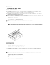
... hardware removal and replacement. NOTICE: Do not perform the following steps unless you replace them to prevent them from the electrical outlet before disconnecting the power supply cables. 3. Back to Contents Page Replacing the Power Supply Dell Studio™ Slim 540s Service Manual CAUTION: Before working inside your computer, read the safety information that secure the...
... hardware removal and replacement. NOTICE: Do not perform the following steps unless you replace them to prevent them from the electrical outlet before disconnecting the power supply cables. 3. Back to Contents Page Replacing the Power Supply Dell Studio™ Slim 540s Service Manual CAUTION: Before working inside your computer, read the safety information that secure the...
Service Manual
Page 35
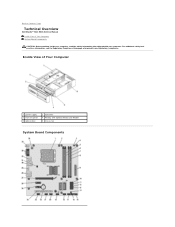
Inside View of Your Computer System Board Components CAUTION: Before working inside your computer, read the safety information that shipped with optional Media Card Reader 6 chassis fan System Board Components Back to Contents Page Technical Overview Dell Studio™ Slim 540s Service Manual Inside View of Your Computer 1 power supply 3 front I/O panel 5 optical drive 2 hard drive 4 FlexBay with your computer. For additional safety best practices information, see the Regulatory Compliance Homepage at www.dell.com/regulatory_compliance.
Inside View of Your Computer System Board Components CAUTION: Before working inside your computer, read the safety information that shipped with optional Media Card Reader 6 chassis fan System Board Components Back to Contents Page Technical Overview Dell Studio™ Slim 540s Service Manual Inside View of Your Computer 1 power supply 3 front I/O panel 5 optical drive 2 hard drive 4 FlexBay with your computer. For additional safety best practices information, see the Regulatory Compliance Homepage at www.dell.com/regulatory_compliance.
Setup Guide
Page 17
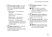
...power supply. 7 USB 2.0 connectors (2) - There may be a problem with the system board. • Solid amber - the computer is blinking. 15 NOTICE: To avoid loss of this button indicates the power state: • Blinking white - Using Your Studio Slim 540s 6 Power button and light - Turns the power... on state. • Blinking amber - the computer is in power-on or off the computer while the hard drive ...
...power supply. 7 USB 2.0 connectors (2) - There may be a problem with the system board. • Solid amber - the computer is blinking. 15 NOTICE: To avoid loss of this button indicates the power state: • Blinking white - Using Your Studio Slim 540s 6 Power button and light - Turns the power... on state. • Blinking amber - the computer is in power-on or off the computer while the hard drive ...
Setup Guide
Page 19
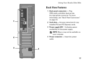
Insert the power cable. 3 4 17 Indicates power availability for any installed PCI and PCI Express cards. 3 Power supply LED - Access connectors for the power supply. Plug USB, audio, and other devices into the appropriate connector. Using Your Studio Slim 540s Back View Features 1 Back panel connectors - NOTE: May or may not be available on page 18. 1 2 Card slots - For more information, see "Back Panel Connectors" on your computer. 2 4 Power connector -
Insert the power cable. 3 4 17 Indicates power availability for any installed PCI and PCI Express cards. 3 Power supply LED - Access connectors for the power supply. Plug USB, audio, and other devices into the appropriate connector. Using Your Studio Slim 540s Back View Features 1 Back panel connectors - NOTE: May or may not be available on page 18. 1 2 Card slots - For more information, see "Back Panel Connectors" on your computer. 2 4 Power connector -
Setup Guide
Page 53
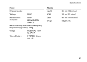
Voltage Coin-cell battery 115/230 VAC. 50/60 Hz, 6 A/3 A 3-V CR2032 lithium coin cell Physical Height Width Depth Weight Specifications 362 mm (14.2 inches) 100 mm (3.9 inches) 435 mm (17.13 inches) 9 kg (19.8 lb.) 51 Power DC power supply: Wattage 250 W Maximum heat dissipation 135 W 62.5 W (ENERGY STAR 4.0) NOTE: Heat dissipation is calculated by using the power supply wattage rating.
Voltage Coin-cell battery 115/230 VAC. 50/60 Hz, 6 A/3 A 3-V CR2032 lithium coin cell Physical Height Width Depth Weight Specifications 362 mm (14.2 inches) 100 mm (3.9 inches) 435 mm (17.13 inches) 9 kg (19.8 lb.) 51 Power DC power supply: Wattage 250 W Maximum heat dissipation 135 W 62.5 W (ENERGY STAR 4.0) NOTE: Heat dissipation is calculated by using the power supply wattage rating.


