Service Manual
Page 1
... States and/or other than its own. Dell Studio One 19/1909 Service Manual Technical Overview Before You Begin Computer Cover Shield Microphone Stand Memory Module(s) Back I/O Panel Processor Fan and Heat Sink Processor Speakers Drives Cards Inverter System Fan and Heat Sink Assembly Side I/O Panel Power Supply Unit Battery System Board Support Assembly Webcam System...
... States and/or other than its own. Dell Studio One 19/1909 Service Manual Technical Overview Before You Begin Computer Cover Shield Microphone Stand Memory Module(s) Back I/O Panel Processor Fan and Heat Sink Processor Speakers Drives Cards Inverter System Fan and Heat Sink Assembly Side I/O Panel Power Supply Unit Battery System Board Support Assembly Webcam System...

Service Manual
Page 11
... Assembly Dell Studio One 19/1909 Service Manual Removing the Support Assembly Replacing the Support Assembly WARNING: Before working inside your computer, read the safety information that secure the support assembly to the LCD panel. 1 screws (14) 2 support assembly 9. Follow the instructions in Before You Begin. 2. Remove the hard drive (see Removing the Power Supply Unit...
... Assembly Dell Studio One 19/1909 Service Manual Removing the Support Assembly Replacing the Support Assembly WARNING: Before working inside your computer, read the safety information that secure the support assembly to the LCD panel. 1 screws (14) 2 support assembly 9. Follow the instructions in Before You Begin. 2. Remove the hard drive (see Removing the Power Supply Unit...

Service Manual
Page 12
... You Begin. 2. Replace the inverter (see Replacing the Hard Drive). 5. Replace the hard drive (see Replacing the Inverter). 8. Replace the side I/O panel (see Replacing the Power Supply Unit). 6. Replace the power supply unit (see Replacing the Side I/O Panel). 9. 1 touch pad cable 3 touch panel cable 2 LVDS cable 4 LCD panel Replacing the Support Assembly 1.
... You Begin. 2. Replace the inverter (see Replacing the Hard Drive). 5. Replace the hard drive (see Replacing the Inverter). 8. Replace the side I/O panel (see Replacing the Power Supply Unit). 6. Replace the power supply unit (see Replacing the Side I/O Panel). 9. 1 touch pad cable 3 touch panel cable 2 LVDS cable 4 LCD panel Replacing the Support Assembly 1.

Service Manual
Page 30
WARNING: Ensure that the part number of the replacement power supply unit matches that secure the power supply unit to Contents Page Power Supply Unit Dell Studio One 19/1909 Service Manual Removing the Power Supply Unit Replacing the Power Supply Unit WARNING: Before working inside your computer, read the safety information that shipped with hardware removal and replacement. Performing these steps incorrectly could damage...
WARNING: Ensure that the part number of the replacement power supply unit matches that secure the power supply unit to Contents Page Power Supply Unit Dell Studio One 19/1909 Service Manual Removing the Power Supply Unit Replacing the Power Supply Unit WARNING: Before working inside your computer, read the safety information that shipped with hardware removal and replacement. Performing these steps incorrectly could damage...

Service Manual
Page 31
Connect the power supply unit cable to the power supply unit. Replace the stand (see Replacing the Computer Cover). Replace the four screws that the protective grounding cable screw is secure. 5. Connect the power plug cable to the connector (ATX_POWER1) on the system board. 4. Follow the procedures in Before You Begin. 2. WARNING: Ensure that secure the power supply unit to Contents Page Replace the computer cover (see Replacing the Stand). 6. Replacing the Power Supply Unit 1. Replace the shield (see Replacing the Shield). 7. Back to the chassis. 3.
Connect the power supply unit cable to the power supply unit. Replace the stand (see Replacing the Computer Cover). Replace the four screws that the protective grounding cable screw is secure. 5. Connect the power plug cable to the connector (ATX_POWER1) on the system board. 4. Follow the procedures in Before You Begin. 2. WARNING: Ensure that secure the power supply unit to Contents Page Replace the computer cover (see Replacing the Stand). 6. Replacing the Power Supply Unit 1. Replace the shield (see Replacing the Shield). 7. Back to the chassis. 3.
Service Manual
Page 50
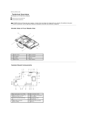
... Compliance Homepage at www.dell.com/regulatory_compliance. Back to Contents Page Technical Overview Dell Studio One 19/1909 Service Manual Inside View of Your Studio One 1 processor fan 3 ...left speaker 5 hard drive 7 optical drive 2 back I/O panel 4 side I/O panel 6 stand 8 right speaker System Board Components 1 password jumper (CLR_PSWD) 3 back I/O panel, PCI Express x4 connector (PCIE_4X_1) 5 inverter connector (INVERTER) 7 optical drive connector (ODD_POWER) 2 LCD connector (LVDS) 4 power supply...
... Compliance Homepage at www.dell.com/regulatory_compliance. Back to Contents Page Technical Overview Dell Studio One 19/1909 Service Manual Inside View of Your Studio One 1 processor fan 3 ...left speaker 5 hard drive 7 optical drive 2 back I/O panel 4 side I/O panel 6 stand 8 right speaker System Board Components 1 password jumper (CLR_PSWD) 3 back I/O panel, PCI Express x4 connector (PCIE_4X_1) 5 inverter connector (INVERTER) 7 optical drive connector (ODD_POWER) 2 LCD connector (LVDS) 4 power supply...

Setup Guide
Page 17
...Studio One 3 Headphone or line-out connector - A flashing light indicates hard drive activity. There may be an issue with either the system board or the power supply. • Solid white - Connects to an audio cable for audio. 5 Hard drive activity light - Turns on or off the computer while the hard drive activity light is a power...your computer. 4 Microphone or line-in sleep state OR the system board cannot start initialization. NOTE: To connect to a powered speaker or sound system, use the line out connector on state. • Blinking amber - CAUTION: To avoid loss of...
...Studio One 3 Headphone or line-out connector - A flashing light indicates hard drive activity. There may be an issue with either the system board or the power supply. • Solid white - Connects to an audio cable for audio. 5 Hard drive activity light - Turns on or off the computer while the hard drive activity light is a power...your computer. 4 Microphone or line-in sleep state OR the system board cannot start initialization. NOTE: To connect to a powered speaker or sound system, use the line out connector on state. • Blinking amber - CAUTION: To avoid loss of...

Setup Guide
Page 28
... another device, such as a lamp. • Contact Dell (see "Contacting Dell" on page 44). There is working by interrupting or 26 If the power light is not responding - Solving Problems Power Problems If the power light is turned on. The computer is either the system board or power supply. Press a key on the keyboard, move the mouse...
... another device, such as a lamp. • Contact Dell (see "Contacting Dell" on page 44). There is working by interrupting or 26 If the power light is not responding - Solving Problems Power Problems If the power light is turned on. The computer is either the system board or power supply. Press a key on the keyboard, move the mouse...


