
Service Manual
Page 1
...change without the written permission of Dell Inc. disclaims any manner whatsoever without notice. © 2008 Dell Inc. Information in trademarks and trade names other countries. Reproduction of these materials in this text: Dell, the DELL logo, and Dell Studio are either trademarks or registered ...or loss of data and tells you make better use of Dell Inc.; A00 Dell Studio™ 540 Service Manual Technical Overview Before You Begin Replacing the Computer Cover Replacing the Front Panel Replacing Memory Module(s) Replacing a PCI/PCI Express Card Replacing Drives Replacing...
...change without the written permission of Dell Inc. disclaims any manner whatsoever without notice. © 2008 Dell Inc. Information in trademarks and trade names other countries. Reproduction of these materials in this text: Dell, the DELL logo, and Dell Studio are either trademarks or registered ...or loss of data and tells you make better use of Dell Inc.; A00 Dell Studio™ 540 Service Manual Technical Overview Before You Begin Replacing the Computer Cover Replacing the Front Panel Replacing Memory Module(s) Replacing a PCI/PCI Express Card Replacing Drives Replacing...

Service Manual
Page 22
... (see System Board Components). 4. Align the notch on the memory module connector. If possible, do not pair an original memory module with the tab on the bottom of matched memory modules installed in DIMM connector 1, the connector closest to Contents Page Replacing Memory Module(s) Dell Studio™ 540 Service Manual CAUTION: Before working inside your computer...
... (see System Board Components). 4. Align the notch on the memory module connector. If possible, do not pair an original memory module with the tab on the bottom of matched memory modules installed in DIMM connector 1, the connector closest to Contents Page Replacing Memory Module(s) Dell Studio™ 540 Service Manual CAUTION: Before working inside your computer...

Service Manual
Page 23
... your computer and devices to electrical outlets, and then turn them on to your Microsoft®Windows® desktop and click Properties. 14. 1 cutouts (2) 3 notch 2 memory module 4 memory module connector NOTICE: To avoid damage to the memory module, press the module straight down into position. If you apply equal force to each end of...
... your computer and devices to electrical outlets, and then turn them on to your Microsoft®Windows® desktop and click Properties. 14. 1 cutouts (2) 3 notch 2 memory module 4 memory module connector NOTICE: To avoid damage to the memory module, press the module straight down into position. If you apply equal force to each end of...

Service Manual
Page 27
...before you disconnect it, so that you touch it. 4. Remove the memory modules (see Replacing Memory Module(s)), make sure that you removed from each cable before you are preset at www.dell.com/regulatory_compliance. For technical assistance, see Replacing the Processor). 6. Follow the...note the routing and location of each memory socket so that the memory modules can get very hot during normal operation. An incorrectly routed or a disconnected cable could damage your computer. Back to Contents Page Replacing the System Board Dell Studio™ 540 Service Manual CAUTION: ...
...before you disconnect it, so that you touch it. 4. Remove the memory modules (see Replacing Memory Module(s)), make sure that you removed from each cable before you are preset at www.dell.com/regulatory_compliance. For technical assistance, see Replacing the Processor). 6. Follow the...note the routing and location of each memory socket so that the memory modules can get very hot during normal operation. An incorrectly routed or a disconnected cable could damage your computer. Back to Contents Page Replacing the System Board Dell Studio™ 540 Service Manual CAUTION: ...

Service Manual
Page 29
... may not appear exactly as the user password l Read the current amount of memory or set the type of the System Setup window. System Setup Options NOTE: Depending... the options that you write down your computer (see the Microsoft® Windows® desktop. Appears on the right side of your computer, including installed hardware, power conservation, and...format. Entering System Setup 1. Press andkeys to navigate. Back to Contents Page System Setup Dell Studio™ 540 Service Manual Overview Clearing Forgotten Passwords Clearing CMOS Settings Flashing the BIOS Overview...
... may not appear exactly as the user password l Read the current amount of memory or set the type of the System Setup window. System Setup Options NOTE: Depending... the options that you write down your computer (see the Microsoft® Windows® desktop. Appears on the right side of your computer, including installed hardware, power conservation, and...format. Entering System Setup 1. Press andkeys to navigate. Back to Contents Page System Setup Dell Studio™ 540 Service Manual Overview Clearing Forgotten Passwords Clearing CMOS Settings Flashing the BIOS Overview...
Service Manual
Page 30
... is bootable, check the device documentation. Auto Power On Enables you see the Microsoft Windows desktop. The items displayed are dynamically updated according to enable or disable the CPU features that are... as options. Exit Exit Options Provides options to the hard drives detected. Insert the memory device into a USB port and restart the computer. Integrated Peripherals Allows you to set...CD/DVD has no operating system is restored. 1. USB Configuration Allows you to run the Dell Diagnostics on the computer when a user tries to boot from the CD/DVD drive to ...
... is bootable, check the device documentation. Auto Power On Enables you see the Microsoft Windows desktop. The items displayed are dynamically updated according to enable or disable the CPU features that are... as options. Exit Exit Options Provides options to the hard drives detected. Insert the memory device into a USB port and restart the computer. Integrated Peripherals Allows you to set...CD/DVD has no operating system is restored. 1. USB Configuration Allows you to run the Dell Diagnostics on the computer when a user tries to boot from the CD/DVD drive to ...

Service Manual
Page 31
... . Connect your computer and devices to enable the password feature. 7. The Boot Device Menu appears, listing all available boot devices. NOTE: To boot to a USB memory key, highlight USB Flash Device and press . On the Boot Device Menu choose the device you want to clear the password. 6. Enter system setup (see...
... . Connect your computer and devices to enable the password feature. 7. The Boot Device Menu appears, listing all available boot devices. NOTE: To boot to a USB memory key, highlight USB Flash Device and press . On the Boot Device Menu choose the device you want to clear the password. 6. Enter system setup (see...
Setup Guide
Page 5
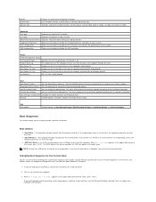
...the Power Buttons on Your Computer and Display 10 Windows Vista Setup 11 Connect to the Internet (Optional 11 Using Your Studio 540 14 Front View Features 14 Back View Features 17 Back Panel Connectors 18 Software Features 20 Solving Problems 22 Network Problems... 22 Power Problems 23 Memory Problems 25 Lockups and Software Problems 26 Using Support Tools 28 Dell Support Center 28 System Messages 29 Hardware Troubleshooter 30 Dell Diagnostics 31 System Recovery Options 33 System Restore 33 Dell Factory Image Restore 34 Operating System Reinstallation ...
...the Power Buttons on Your Computer and Display 10 Windows Vista Setup 11 Connect to the Internet (Optional 11 Using Your Studio 540 14 Front View Features 14 Back View Features 17 Back Panel Connectors 18 Software Features 20 Solving Problems 22 Network Problems... 22 Power Problems 23 Memory Problems 25 Lockups and Software Problems 26 Using Support Tools 28 Dell Support Center 28 System Messages 29 Hardware Troubleshooter 30 Dell Diagnostics 31 System Recovery Options 33 System Restore 33 Dell Factory Image Restore 34 Operating System Reinstallation ...

Setup Guide
Page 18
...12 FlexBay drive - Can contain an optional FlexBay. 13 USB 2.0 connectors (2) - Connects USB devices that are connected occasionally such as memory keys, digital cameras, and MP3 players. 14 Optional Optical drive bay - Slide up the front panel door grip to view and share ...following digital memory cards: • Secure Digital (SD) memory card • Secure Digital High Capacity (SDHC) card • Multi Media Card (MMC) • Memory Stick • Memory Stick PRO • xD-Picture Card (type - Can contain an additional optical drive. 16 Using Your Studio 540 ...
...12 FlexBay drive - Can contain an optional FlexBay. 13 USB 2.0 connectors (2) - Connects USB devices that are connected occasionally such as memory keys, digital cameras, and MP3 players. 14 Optional Optical drive bay - Slide up the front panel door grip to view and share ...following digital memory cards: • Secure Digital (SD) memory card • Secure Digital High Capacity (SDHC) card • Multi Media Card (MMC) • Memory Stick • Memory Stick PRO • xD-Picture Card (type - Can contain an additional optical drive. 16 Using Your Studio 540 ...

Setup Guide
Page 26
... not be malfunctioning or incorrectly installed. The display may have to remove and then reinstall the memory modules (for information on removing and replacing memory modules, see "Contacting Dell" on . If you encounter interference that the display is receiving electrical power, but a device... might be connected or powered on the Dell Support website at support.dell.com). Solving Problems If the ...
... not be malfunctioning or incorrectly installed. The display may have to remove and then reinstall the memory modules (for information on removing and replacing memory modules, see "Contacting Dell" on . If you encounter interference that the display is receiving electrical power, but a device... might be connected or powered on the Dell Support website at support.dell.com). Solving Problems If the ...
Setup Guide
Page 27
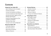
... that your computer is successfully communicating with the memory. 25 If necessary, install additional memory (see the Service Manual on the Dell Support website at support.dell.com). • Reseat the memory modules (see the Service Manual on the Dell Support website at support.dell.com). • Check if the memory module is compatible with your computer. Your...
... that your computer is successfully communicating with the memory. 25 If necessary, install additional memory (see the Service Manual on the Dell Support website at support.dell.com). • Reseat the memory modules (see the Service Manual on the Dell Support website at support.dell.com). • Check if the memory module is compatible with your computer. Your...
Setup Guide
Page 46
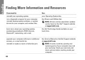
... files. the Service Manual on your computer with new or additional memory, or a new hard drive. run a diagnostic program for your computer, reinstall desktop system software, or update drivers for your warranty. the Dell Technology Guide available on the Dell Support website at support.dell.com. upgrade your hard drive. See: your operating system, maintaining...
... files. the Service Manual on your computer with new or additional memory, or a new hard drive. run a diagnostic program for your computer, reinstall desktop system software, or update drivers for your warranty. the Dell Technology Guide available on the Dell Support website at support.dell.com. upgrade your hard drive. See: your operating system, maintaining...

Setup Guide
Page 49
... Disc RW optical drive one 3.5 inch bay for FlexBay Internally accessible two 3.5-inch drive bays for SATA hard drive Memory Connectors Capacities four internallyaccessible DDR2 DIMM sockets 512 MB, 1 GB, and 2 GB Specifications Memory Memory type 800 MHz, DDR2 DIMM Minimum 1 GB Maximum 4 GB (32-bit operating system) 8 GB (64-bit operating system...
... Disc RW optical drive one 3.5 inch bay for FlexBay Internally accessible two 3.5-inch drive bays for SATA hard drive Memory Connectors Capacities four internallyaccessible DDR2 DIMM sockets 512 MB, 1 GB, and 2 GB Specifications Memory Memory type 800 MHz, DDR2 DIMM Minimum 1 GB Maximum 4 GB (32-bit operating system) 8 GB (64-bit operating system...

Setup Guide
Page 58
Index ISP Internet Service Provider 11 L line-in connector 15 M media card reader 16 memory minimum and maximum 47 memory problems solving 25 Memory Stick reader 16 memory support 47 microphone connector 15 Microsoft Windows Vista 11 MMC 16 Multi Media Card reader 16 56 N network connection fixing 23 network connector location 18 network speed testing 22 O order status 40 P power button and light 15 power connector 17 power problems, solving 23 problems, solving 22 processor 46 products information and purchasing 40
Index ISP Internet Service Provider 11 L line-in connector 15 M media card reader 16 memory minimum and maximum 47 memory problems solving 25 Memory Stick reader 16 memory support 47 microphone connector 15 Microsoft Windows Vista 11 MMC 16 Multi Media Card reader 16 56 N network connection fixing 23 network connector location 18 network speed testing 22 O order status 40 P power button and light 15 power connector 17 power problems, solving 23 problems, solving 22 processor 46 products information and purchasing 40


