EMC PowerSwitch S5200F-ON Series Setup Guide
Page 3
...8 Unpack...8 Ground cable...9 Rack or cabinet installation...9 One-half U front-rack installation...10 One-half U switch installation...11 One-half U switch removal...12 One U ReadyRails installation...12 1U Tool-less mount installation...13 Two-post flush-mount installation...14 Two...threaded installation...15 S5200F-ON Series switch installation...16 Two U four-post rack assembly...18 Four-post rack mount...18 DC power connections...19 S5212F-ON only DC power connections...21 Optics installation...22 Optics removal...22 Switch start up...22 After switch installation...22 4 Specifications...23 ...
...8 Unpack...8 Ground cable...9 Rack or cabinet installation...9 One-half U front-rack installation...10 One-half U switch installation...11 One-half U switch removal...12 One U ReadyRails installation...12 1U Tool-less mount installation...13 Two-post flush-mount installation...14 Two...threaded installation...15 S5200F-ON Series switch installation...16 Two U four-post rack assembly...18 Four-post rack mount...18 DC power connections...19 S5212F-ON only DC power connections...21 Optics installation...22 Optics removal...22 Switch start up...22 After switch installation...22 4 Specifications...23 ...
EMC PowerSwitch S5200F-ON Series Setup Guide
Page 4
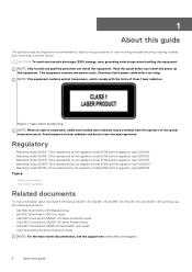
... information about the S5200F-ON Series (S5232F-ON, S5248F-ON, S5296F-ON, S5224F-ON, and S5212F-ON) switches, see the following documents. • Dell EMC SmartFabric OS10 Release Notes • Dell EMC SmartFabric OS10 User Guide • Delll EMC PowerSwitch S5200F-ON Series Installation Guide • Delll... E21W003. • Marketing model S5296F-ON is represented by the regulatory model E26W and the regulatory type E26W001. • Marketing model S5212F-ON is connected, visible and invisible laser radiation may be emitted from the aperture of Class 1 laser radiation. 1 About this guide ...
... information about the S5200F-ON Series (S5232F-ON, S5248F-ON, S5296F-ON, S5224F-ON, and S5212F-ON) switches, see the following documents. • Dell EMC SmartFabric OS10 Release Notes • Dell EMC SmartFabric OS10 User Guide • Delll EMC PowerSwitch S5200F-ON Series Installation Guide • Delll... E21W003. • Marketing model S5296F-ON is represented by the regulatory model E26W and the regulatory type E26W001. • Marketing model S5212F-ON is connected, visible and invisible laser radiation may be emitted from the aperture of Class 1 laser radiation. 1 About this guide ...
EMC PowerSwitch S5200F-ON Series Setup Guide
Page 6
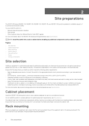
... see Site selection. 2 Site preparations The 5200F-ON Series (S5232F-ON, S5248F-ON, S5296F-ON, S5224F-ON, and S5212F-ON) switch is suitable for the location controls access to the restricted area. Rack mounting When you install your area uses. The authority ...installation as cables or optics. For cabinet placement requirements, see Specifications. Ensure that the rack is a minimum of security. NOTE: Install the switch into a rack or cabinet before installing any additional components such as part of the National Electrical Code and NFPA 75. You can only gain...
... see Site selection. 2 Site preparations The 5200F-ON Series (S5232F-ON, S5248F-ON, S5296F-ON, S5224F-ON, and S5212F-ON) switch is suitable for the location controls access to the restricted area. Rack mounting When you install your area uses. The authority ...installation as cables or optics. For cabinet placement requirements, see Specifications. Ensure that the rack is a minimum of security. NOTE: Install the switch into a rack or cabinet before installing any additional components such as part of the National Electrical Code and NFPA 75. You can only gain...
EMC PowerSwitch S5200F-ON Series Setup Guide
Page 7
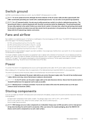
...the fans. The fan speed varies based on internal temperature monitoring. When installing AC or DC switches, follow the requirements of the AC power cable provides a ground path, Dell EMC recommends grounding your site's ventilation. Before servicing, ensure that all components following configurations: ...an ESD-preventive wrist or heel ground strap when handling the switch and its components on the stock keeping unit (SKU) type. Switch ground Dell EMC recommends grounding your switch. The S5200F-ON Series switch has SKUs that the socket-outlet is located/installed near each...
...the fans. The fan speed varies based on internal temperature monitoring. When installing AC or DC switches, follow the requirements of the AC power cable provides a ground path, Dell EMC recommends grounding your site's ventilation. Before servicing, ensure that all components following configurations: ...an ESD-preventive wrist or heel ground strap when handling the switch and its components on the stock keeping unit (SKU) type. Switch ground Dell EMC recommends grounding your switch. The S5200F-ON Series switch has SKUs that the socket-outlet is located/installed near each...
EMC PowerSwitch S5200F-ON Series Setup Guide
Page 8
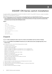
... • Safety and Regulatory Information • Warranty and Support Information 1. NOTE: For the S5212F-ON and S5296F-ON switches only: the USB extension cable is packaged separately. male to female • S5212F-ON: Two fixed fan units • S5296F-ON: one USB extension cable; Open the ...To install the S5200F-ON Series (S5232F-ON, S5248F-ON, S5296F-ON, S5224F-ON, and S5212F-ON) switch, complete the installation procedures in the order presented in this switch. Avoid dropping the switch or any evidence of this type, take all packing material. 5. Always wear an ESD-preventive...
... • Safety and Regulatory Information • Warranty and Support Information 1. NOTE: For the S5212F-ON and S5296F-ON switches only: the USB extension cable is packaged separately. male to female • S5212F-ON: Two fixed fan units • S5296F-ON: one USB extension cable; Open the ...To install the S5200F-ON Series (S5232F-ON, S5248F-ON, S5296F-ON, S5224F-ON, and S5212F-ON) switch, complete the installation procedures in the order presented in this switch. Avoid dropping the switch or any evidence of this type, take all packing material. 5. Always wear an ESD-preventive...
EMC PowerSwitch S5200F-ON Series Setup Guide
Page 9
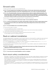
... conductors. Use care not to the wanted length. Ground cable To attach a ground cable to the switch, use the ReadyRails system for the S5296F-ON or S5212F-ON switches. Before you install multiple electrical components in a plastic bag placed with a dedicated ground wire. The ... of the AC power cable provides a ground path, Dell EMC recommends grounding your rack's load rating. • Power considerations-Connect only to represent a specific switch. The ground lug bracket screws ship attached to the switch: 1. Rack mounting for grounding. Overloaded power sources and...
... conductors. Use care not to the wanted length. Ground cable To attach a ground cable to the switch, use the ReadyRails system for the S5296F-ON or S5212F-ON switches. Before you install multiple electrical components in a plastic bag placed with a dedicated ground wire. The ... of the AC power cable provides a ground path, Dell EMC recommends grounding your rack's load rating. • Power considerations-Connect only to represent a specific switch. The ground lug bracket screws ship attached to the switch: 1. Rack mounting for grounding. Overloaded power sources and...
EMC PowerSwitch S5200F-ON Series Setup Guide
Page 10
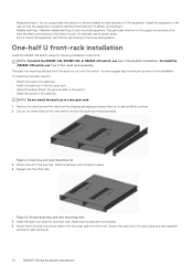
...reliable earthing of the equipment. Attach the front dual-tray switch rails to the dual tray. One-half U front-rack installation Install the S5212F-ON switch using two user-supplied screws for each rack post. 10 S5200F-ON Series switch Installation NOTE: To install the S5232F-ON, S5248F-ON..., or S5224F-ON switch, see Two U four-post rack assembly. To install the one-half U switch: • Attach the ...
...reliable earthing of the equipment. Attach the front dual-tray switch rails to the dual tray. One-half U front-rack installation Install the S5212F-ON switch using two user-supplied screws for each rack post. 10 S5200F-ON Series switch Installation NOTE: To install the S5232F-ON, S5248F-ON..., or S5224F-ON switch, see Two U four-post rack assembly. To install the one-half U switch: • Attach the ...
EMC PowerSwitch S5200F-ON Series Setup Guide
Page 11
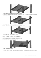
...slot from the rear. Install one or two half-U switches in the four-post rack-mounted dual tray. 1. S5200F-ON Series switch Installation 11 Attach the dual-tray front to the four-post rack from the front. Figure 6. Attach the rear dual-tray switch rails to the four-post rack front 7. Secure ...the dual-tray in the four-post rack One-half U switch installation Install one -half U switch The switch is fully inserted when it presses the stop feature on the dual tray. Figure 7. Tighten all mounting screws to the rack using two user-supplied...
...slot from the rear. Install one or two half-U switches in the four-post rack-mounted dual tray. 1. S5200F-ON Series switch Installation 11 Attach the dual-tray front to the four-post rack from the front. Figure 6. Attach the rear dual-tray switch rails to the four-post rack front 7. Secure ...the dual-tray in the four-post rack One-half U switch installation Install one -half U switch The switch is fully inserted when it presses the stop feature on the dual tray. Figure 7. Tighten all mounting screws to the rack using two user-supplied...
EMC PowerSwitch S5200F-ON Series Setup Guide
Page 12
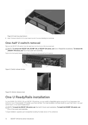
...three possible 1U threaded round-hole methods. Figure 8. Dual-tray stop feature 2. One-half U switch removal Remove the S5212F-ON switch from the dual tray from the front of the four-post rack. Figure 9. Switch release latches Figure 10. The tooled installation methods include two-post flush mount, two-post center...install the ReadyRails system using the 1U tool-less square-hole method or one of the outside rail. 12 S5200F-ON Series switch Installation NOTE: To install the S5212F-ON switch, see Two U four-post rack assembly. NOTE: To remove the S5232F-ON, S5248F-ON, or S5224F-ON...
...three possible 1U threaded round-hole methods. Figure 8. Dual-tray stop feature 2. One-half U switch removal Remove the S5212F-ON switch from the dual tray from the front of the four-post rack. Figure 9. Switch release latches Figure 10. The tooled installation methods include two-post flush mount, two-post center...install the ReadyRails system using the 1U tool-less square-hole method or one of the outside rail. 12 S5200F-ON Series switch Installation NOTE: To install the S5212F-ON switch, see Two U four-post rack assembly. NOTE: To remove the S5232F-ON, S5248F-ON, or S5224F-ON...
EMC PowerSwitch S5200F-ON Series Setup Guide
Page 13
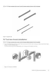
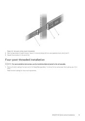
... the ReadyRails flange ears facing outward. Place one rail between the left and right vertical posts. Figure 12. 1U tool-less installation S5200F-ON Series switch Installation 13 Figure 11. NOTE: For more installation instructions, see the installation labels attached to the rail assembly. 1. Separate rails 1U Tool-less mount installation...
... the ReadyRails flange ears facing outward. Place one rail between the left and right vertical posts. Figure 12. 1U tool-less installation S5200F-ON Series switch Installation 13 Figure 11. NOTE: For more installation instructions, see the installation labels attached to the rail assembly. 1. Separate rails 1U Tool-less mount installation...
EMC PowerSwitch S5200F-ON Series Setup Guide
Page 14
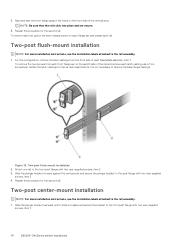
... forward against the vertical post and secure the plunger bracket to the front post flange with two user-supplied screws, item 1. 14 S5200F-ON Series switch Installation 2. Align and seat the front flange pegs in the holes on each flange ear and unseat each front flange ear on the... switch side of the vertical post. Figure 13. For this procedure for the second rail. It is not necessary to the rail assembly. 1. Retain the latch ...
... forward against the vertical post and secure the plunger bracket to the front post flange with two user-supplied screws, item 1. 14 S5200F-ON Series switch Installation 2. Align and seat the front flange pegs in the holes on each flange ear and unseat each front flange ear on the... switch side of the vertical post. Figure 13. For this procedure for the second rail. It is not necessary to the rail assembly. 1. Retain the latch ...
EMC PowerSwitch S5200F-ON Series Setup Guide
Page 15
.... Remove the latch castings from each latch casting, use a Torx driver. To remove the two screws each end of the ReadyRails assemblies. S5200F-ON Series switch Installation 15 Repeat this procedure for future rack requirements. Figure 14. Two-post center-mount installation 2. Slide the back bracket towards the post.
.... Remove the latch castings from each latch casting, use a Torx driver. To remove the two screws each end of the ReadyRails assemblies. S5200F-ON Series switch Installation 15 Repeat this procedure for future rack requirements. Figure 14. Two-post center-mount installation 2. Slide the back bracket towards the post.
EMC PowerSwitch S5200F-ON Series Setup Guide
Page 16
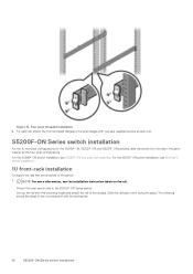
... For the 1U two-post configurations for the S5248F-ON, S5232F-ON, and S5224F-ON switches, slide the switch into place. For each end. For the S5212F-ON switch installation, see S5296F-ON four-post rack assembly. Slide the rail back until it locks into the rails in the same manner as the four...
... For the 1U two-post configurations for the S5248F-ON, S5232F-ON, and S5224F-ON switches, slide the switch into place. For each end. For the S5212F-ON switch installation, see S5296F-ON four-post rack assembly. Slide the rail back until it locks into the rails in the same manner as the four...
EMC PowerSwitch S5200F-ON Series Setup Guide
Page 17
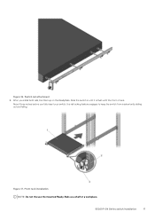
After you fully insert your switch, the rail locking feature engages to keep the switch from inadvertently sliding out and falling. Figure 16. Figure 17. Front rack installation NOTE: Do not the use the mounted Ready-Rails as a shelf or a workplace. About three inches before you install both rails, line them up on the ReadyRails. S5200F-ON Series switch Installation 17 Slide the switch in until it is flush with the front of rack. Switch rail attachment 2.
After you fully insert your switch, the rail locking feature engages to keep the switch from inadvertently sliding out and falling. Figure 16. Figure 17. Front rack installation NOTE: Do not the use the mounted Ready-Rails as a shelf or a workplace. About three inches before you install both rails, line them up on the ReadyRails. S5200F-ON Series switch Installation 17 Slide the switch in until it is flush with the front of rack. Switch rail attachment 2.
EMC PowerSwitch S5200F-ON Series Setup Guide
Page 18
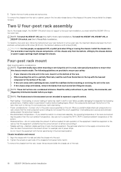
... install the stabilizers before loading begins. Read the safety instructions in a rack, ensure that the chassis remains stable. When you install the switch in shelf or rack failure, possibly damaging the equipment and causing personal injury. use of rack-mounted equipment. To install in a four-...the branch circuit, for safe operation of the rack. 18 S5200F-ON Series switch Installation NOTE: To install the S5212F-ON, see One U ReadyRails installation. To install the S5232F-ON, S5248F-ON, or S5224F-ON switch, see One-half U front-rack installation. Lift the chassis only from ...
... install the stabilizers before loading begins. Read the safety instructions in a rack, ensure that the chassis remains stable. When you install the switch in shelf or rack failure, possibly damaging the equipment and causing personal injury. use of rack-mounted equipment. To install in a four-...the branch circuit, for safe operation of the rack. 18 S5200F-ON Series switch Installation NOTE: To install the S5212F-ON, see One U ReadyRails installation. To install the S5232F-ON, S5248F-ON, or S5224F-ON switch, see One-half U front-rack installation. Lift the chassis only from ...
EMC PowerSwitch S5200F-ON Series Setup Guide
Page 19
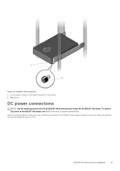
To connect DC power to restrict front-back movement of the switch. 2. Each DC powered system comes with a set is provided for the S5212F-ON switch. S5296F-ON installation 1. One set containing a prewired (3-inch 8AWG) power supply connector and a four-screw wiring block. S5200F-ON Series switch Installation 19 Main screw DC power connections NOTE: Use the following instructions for all S5200F-ON Series switches except for each DC PSU. Figure 18. Extra screws to the S5212F-ON switch, see S5212F-ON only DC power connections.
To connect DC power to restrict front-back movement of the switch. 2. Each DC powered system comes with a set is provided for the S5212F-ON switch. S5296F-ON installation 1. One set containing a prewired (3-inch 8AWG) power supply connector and a four-screw wiring block. S5200F-ON Series switch Installation 19 Main screw DC power connections NOTE: Use the following instructions for all S5200F-ON Series switches except for each DC PSU. Figure 18. Extra screws to the S5212F-ON switch, see S5212F-ON only DC power connections.
EMC PowerSwitch S5200F-ON Series Setup Guide
Page 20
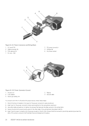
... lengths into the wiring block. 4. Captive screws (2) 5. Insert each of the power connector's left and right levered clamps lock into place. 20 S5200F-ON Series switch Installation Figure 19. DC Power Connector and Wiring Block 1. Secure the site's DC power source wires to the site's DC power source, follow these steps...
... lengths into the wiring block. 4. Captive screws (2) 5. Insert each of the power connector's left and right levered clamps lock into place. 20 S5200F-ON Series switch Installation Figure 19. DC Power Connector and Wiring Block 1. Secure the site's DC power source wires to the site's DC power source, follow these steps...
EMC PowerSwitch S5200F-ON Series Setup Guide
Page 21
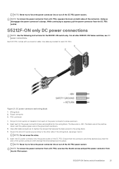
...block 2. PSU connector 1. Insert the DC power connector into the wiring block. 4. S5200F-ON Series switch Installation 21 Power connector 3. Use a flat-blade screwdriver to force the power connector into the wiring block... positive return, and the yellow/green wire is provided for the S5212F-ON switch only. Strip a 1/2 inch section of insulation from each of the power connector's wires, as shown.... 3. Insert each DC PSU. S5212F-ON only DC power connections...
...block 2. PSU connector 1. Insert the DC power connector into the wiring block. 4. S5200F-ON Series switch Installation 21 Power connector 3. Use a flat-blade screwdriver to force the power connector into the wiring block... positive return, and the yellow/green wire is provided for the S5212F-ON switch only. Strip a 1/2 inch section of insulation from each of the power connector's wires, as shown.... 3. Insert each DC PSU. S5212F-ON only DC power connections...
EMC PowerSwitch S5200F-ON Series Setup Guide
Page 22
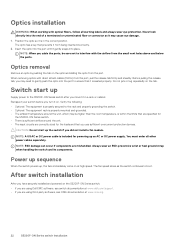
....org. 22 S5200F-ON Series switch Installation After switch installation After you have securely installed and powered on . Insert the optic into the port to gently push the optic into the port until it on the S5200F-ON Series switch: • If you are using Dell EMC software, see ONIE documentation ...at www.dell.com/support. • If you did not install a fan module. NOTE: A US AC or DC power ...
....org. 22 S5200F-ON Series switch Installation After switch installation After you have securely installed and powered on . Insert the optic into the port to gently push the optic into the port until it on the S5200F-ON Series switch: • If you are using Dell EMC software, see ONIE documentation ...at www.dell.com/support. • If you did not install a fan module. NOTE: A US AC or DC power ...
EMC PowerSwitch S5200F-ON Series Setup Guide
Page 23
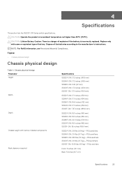
... S5248F-ON: 21.4 lbs (9.7 kg)-PSUs and fans S5296F-ON: 33.3 lbs (15.1 kg)-PSUs and fans S5224F-ON: 21.4 lbs (9.7 kg)-PSUs and fans S5212F-ON: 10.05 lbs (4.5 kg)-PSUs and fans Front: 5 inches (12.7 cm) Back: 5 inches (12.7 cm) Specifications 23 Topics: • Chassis physical design ...Depth Chassis weight with same or equivalent type of the batteries according to the manufacturer's instructions. 4 Specifications This section lists the S5200F-ON Series switch specifications. CAUTION: Lithium Battery Caution: There is a danger of explosion if the battery is incorrectly replaced.
... S5248F-ON: 21.4 lbs (9.7 kg)-PSUs and fans S5296F-ON: 33.3 lbs (15.1 kg)-PSUs and fans S5224F-ON: 21.4 lbs (9.7 kg)-PSUs and fans S5212F-ON: 10.05 lbs (4.5 kg)-PSUs and fans Front: 5 inches (12.7 cm) Back: 5 inches (12.7 cm) Specifications 23 Topics: • Chassis physical design ...Depth Chassis weight with same or equivalent type of the batteries according to the manufacturer's instructions. 4 Specifications This section lists the S5200F-ON Series switch specifications. CAUTION: Lithium Battery Caution: There is a danger of explosion if the battery is incorrectly replaced.


