User Manual
Page 2
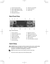
9. mouse connector 2. keyboard connector 9. For additional best practices information, see www.dell.com/regulatory_compliance. Connect the monitor using only one of the procedures in /microphone connector Quick Setup WARNING: Before ...light 3. VGA connector 13. NOTE: Some devices may not be included if you begin any of the following cables: 2 power connector 13. network connector 4. DisplayPort connectors (2) 11. power supply diagnostic button 12. serial connector 7. security-cable slot 16. Back Panel View 1. USB 2.0 connectors (2) 6. back panel connectors...
9. mouse connector 2. keyboard connector 9. For additional best practices information, see www.dell.com/regulatory_compliance. Connect the monitor using only one of the procedures in /microphone connector Quick Setup WARNING: Before ...light 3. VGA connector 13. NOTE: Some devices may not be included if you begin any of the following cables: 2 power connector 13. network connector 4. DisplayPort connectors (2) 11. power supply diagnostic button 12. serial connector 7. security-cable slot 16. Back Panel View 1. USB 2.0 connectors (2) 6. back panel connectors...

User Manual
Page 4
...; Help and Support and select the option to ship with your computer. Figure 8. Press the power buttons on the monitor and the computer. The following specifications are only those required by using the power supply wattage rating. 4 Power Voltage Wattage Input Current Coin-cell battery Maximum heat dissipation 100 VAC to 240 VAC 275...
...; Help and Support and select the option to ship with your computer. Figure 8. Press the power buttons on the monitor and the computer. The following specifications are only those required by using the power supply wattage rating. 4 Power Voltage Wattage Input Current Coin-cell battery Maximum heat dissipation 100 VAC to 240 VAC 275...

Owner's manual
Page 3
... the Hard Drive...13 Removing the Optical Drive...13 Installing the Optical Drive...15 Removing the Speakers...15 Installing the Speakers...16 Removing the Power Supply...16 Installing the Power Supply...19 Removing the Heat Sink...19 Installing the Heat Sink...20 Removing the Processor...21 Installing the Processor...21 Removing the System Fan...
... the Hard Drive...13 Removing the Optical Drive...13 Installing the Optical Drive...15 Removing the Speakers...15 Installing the Speakers...16 Removing the Power Supply...16 Installing the Power Supply...19 Removing the Heat Sink...19 Installing the Heat Sink...20 Removing the Processor...21 Installing the Processor...21 Removing the System Fan...
Owner's manual
Page 16
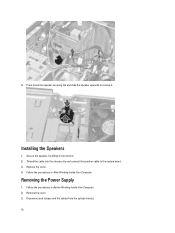
Replace the cover. 4. Disconnect and release and the cables from the optical drive(s). 16 Follow the procedures in Before Working Inside Your Computer. 2. Removing the Power Supply 1. Follow the procedures in After Working Inside Your Computer. Remove the cover. 3. Thread the cable into the slot. 2. Press down the speaker-securing tab and slide the speaker upwards to remove it into the chassis clip and connect the speaker cable to the system board. 3. Secure the speaker, by sliding it . 4. Installing the Speakers 1.
Replace the cover. 4. Disconnect and release and the cables from the optical drive(s). 16 Follow the procedures in Before Working Inside Your Computer. 2. Removing the Power Supply 1. Follow the procedures in After Working Inside Your Computer. Remove the cover. 3. Thread the cable into the slot. 2. Press down the speaker-securing tab and slide the speaker upwards to remove it into the chassis clip and connect the speaker cable to the system board. 3. Secure the speaker, by sliding it . 4. Installing the Speakers 1.

Owner's manual
Page 18
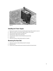
Figure 16. 7. Press the release tab at the bottom of the power supply and slide the power supply towards the front of the computer. 18 Figure 17. 8. 6. Lift the power supply out of the computer. Remove the screws that secure the power supply unit to the computer.
Figure 16. 7. Press the release tab at the bottom of the power supply and slide the power supply towards the front of the computer. 18 Figure 17. 8. 6. Lift the power supply out of the computer. Remove the screws that secure the power supply unit to the computer.
Owner's manual
Page 19
...disconnect the heat-sink cable from the system board. 19 Follow the procedures in Before Working Inside Your Computer. 2. Tighten the screws to secure the power supply to the back of the computer to the hard drives(s) and optical drive(s). 6. Install the cover. 7. Press the clip to the system board.... 4. Figure 18. Removing the Heat Sink 1. Follow the procedures in After Working Inside Your Computer. Installing the Power Supply 1. Thread the power cables into the chassis clips. 5. Connect the power cables to secure it. 2. Remove the cover. 3.
...disconnect the heat-sink cable from the system board. 19 Follow the procedures in Before Working Inside Your Computer. 2. Tighten the screws to secure the power supply to the back of the computer to the hard drives(s) and optical drive(s). 6. Install the cover. 7. Press the clip to the system board.... 4. Figure 18. Removing the Heat Sink 1. Follow the procedures in After Working Inside Your Computer. Installing the Power Supply 1. Thread the power cables into the chassis clips. 5. Connect the power cables to secure it. 2. Remove the cover. 3.

Owner's manual
Page 38
Allows the Intel TurboBoost driver to AC power supply. 38 Description Specifies how the computer will not automatically power up from standby. • Enable USB Wake Support - The system will respond when AC power is unaffected by a special LAN signal. This option allows you specified above. • Select Days... or disable the Hyper-Threading technology. You can be enabled in standard 12-hour format (hour:minutes:seconds). The system will power up every day at the time you to define the controls when Deep Sleep is set the AC Recovery to disabled. Controls ...
Allows the Intel TurboBoost driver to AC power supply. 38 Description Specifies how the computer will not automatically power up from standby. • Enable USB Wake Support - The system will respond when AC power is unaffected by a special LAN signal. This option allows you specified above. • Select Days... or disable the Hyper-Threading technology. You can be enabled in standard 12-hour format (hour:minutes:seconds). The system will power up every day at the time you to define the controls when Deep Sleep is set the AC Recovery to disabled. Controls ...
Owner's manual
Page 45
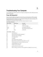
...diagnostic LED is only active and visible during the operation of the computer. The repeated pattern has a long pause inserted in sleep state blinking off power supply unit (PSU) failure steady off PSU is working but a memory configuration or compatibility error has occurred 45 For example 2,3 = 2 amber blinks, short ..., it is 2 or 3 blinks followed by long pause then repeats. The pattern is no longer visible. Amber LED blinking scheme - Power LED Diagnostics The power button LED located on the front of blinks up to fetch code off steady system is in the middle...
...diagnostic LED is only active and visible during the operation of the computer. The repeated pattern has a long pause inserted in sleep state blinking off power supply unit (PSU) failure steady off PSU is working but a memory configuration or compatibility error has occurred 45 For example 2,3 = 2 amber blinks, short ..., it is 2 or 3 blinks followed by long pause then repeats. The pattern is no longer visible. Amber LED blinking scheme - Power LED Diagnostics The power button LED located on the front of blinks up to fetch code off steady system is in the middle...

Owner's manual
Page 53
...°C to 65 °C (-40 °F to 149 °F) 20% to 80% (non-condensing) 5% to the power connector (at the back of the power system by using the power supply wattage rating. The power cable must be connected to 95% (non-condensing) 0.26 GRMS 53 Table 26. NOTE: You can test the health... 5.0 A 275 W/320 W 4774.00 BTU/hr NOTE: Heat dissipation is within specification, the self-test LED lights up , the power supply may be defective. AC power must be connected during this test. The power supply is turned on and is functional. If the LED does not light up . Table 25. Feature...
...°C to 65 °C (-40 °F to 149 °F) 20% to 80% (non-condensing) 5% to the power connector (at the back of the power system by using the power supply wattage rating. The power cable must be connected to 95% (non-condensing) 0.26 GRMS 53 Table 26. NOTE: You can test the health... 5.0 A 275 W/320 W 4774.00 BTU/hr NOTE: Heat dissipation is within specification, the self-test LED lights up , the power supply may be defective. AC power must be connected during this test. The power supply is turned on and is functional. If the LED does not light up . Table 25. Feature...


