
User Manual
Page 1
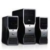
optical drive Regulatory Model: D09M Regulatory Type: D09M004 2012 - 04 Dell Precision T1650 Setup And Features Information About Warnings WARNING: A WARNING indicates a potential for property damage, personal injury, or death. power button, power light 2. headphone connector 4. Front And Back View Figure 1. Front and Back View 1. optical-drive bay 3. USB 3.0 connectors (2) 6. drive activity light 8. USB 2.0 connectors (2) 7. microphone connector 5.
optical drive Regulatory Model: D09M Regulatory Type: D09M004 2012 - 04 Dell Precision T1650 Setup And Features Information About Warnings WARNING: A WARNING indicates a potential for property damage, personal injury, or death. power button, power light 2. headphone connector 4. Front And Back View Figure 1. Front and Back View 1. optical-drive bay 3. USB 3.0 connectors (2) 6. drive activity light 8. USB 2.0 connectors (2) 7. microphone connector 5.
User Manual
Page 2
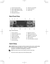
.... mouse connector 2. network activity light 5. For additional best practices information, see www.dell.com/regulatory_compliance. NOTE: Some devices may not be included if you begin any of the following cables: 2 security-cable slot 16. DisplayPort connectors (2) 11. VGA connector 13. Connect the monitor using only one of the procedures in /microphone connector Quick Setup WARNING: Before you did not order them. 1. power connector 13. line-out connector 8. optical-drive eject button 10. USB 3.0 connectors (2) 12. keyboard connector 9. serial connector...
.... mouse connector 2. network activity light 5. For additional best practices information, see www.dell.com/regulatory_compliance. NOTE: Some devices may not be included if you begin any of the following cables: 2 security-cable slot 16. DisplayPort connectors (2) 11. VGA connector 13. Connect the monitor using only one of the procedures in /microphone connector Quick Setup WARNING: Before you did not order them. 1. power connector 13. line-out connector 8. optical-drive eject button 10. USB 3.0 connectors (2) 12. keyboard connector 9. serial connector...
User Manual
Page 3
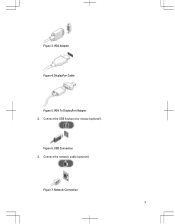
Network Connection 3 VGA Adapter Figure 4. DisplayPort Cable Figure 5. Connect the network cable (optional). Figure 3. Figure 6. Figure 7. VGA To DisplayPort Adapter 2. USB Connection 3. Connect the USB keyboard or mouse (optional).
Network Connection 3 VGA Adapter Figure 4. DisplayPort Cable Figure 5. Connect the network cable (optional). Figure 3. Figure 6. Figure 7. VGA To DisplayPort Adapter 2. USB Connection 3. Connect the USB keyboard or mouse (optional).

Owner's manual
Page 3
... Cover...7 Removing the Intrusion Switch...8 Installing the Intrusion Switch...8 Removing the Front Panel...9 Installing the Front Panel...10 Removing the Expansion Card...10 Installing the Expansion Card...11 Memory Module Guidelines...11 Removing the Memory...11 Installing the Memory...11 Removing the Coin-Cell Battery...12 Installing the Coin-Cell Battery...12 Removing the Hard Drive...12 Installing the Hard Drive...13 Removing the Optical Drive...13 Installing the Optical Drive...15 Removing the Speakers...15 Installing the Speakers...16 Removing the Power Supply...16 Installing the Power...
... Cover...7 Removing the Intrusion Switch...8 Installing the Intrusion Switch...8 Removing the Front Panel...9 Installing the Front Panel...10 Removing the Expansion Card...10 Installing the Expansion Card...11 Memory Module Guidelines...11 Removing the Memory...11 Installing the Memory...11 Removing the Coin-Cell Battery...12 Installing the Coin-Cell Battery...12 Removing the Hard Drive...12 Installing the Hard Drive...13 Removing the Optical Drive...13 Installing the Optical Drive...15 Removing the Speakers...15 Installing the Speakers...16 Removing the Power Supply...16 Installing the Power...

Owner's manual
Page 4
... Installing the System Board...31 System Board Components...32 3 System Setup...33 Boot Sequence...33 Navigation Keys...33 System Setup Options...34 Updating the BIOS ...40 Jumper Settings...40 System and Setup Password...41 Assigning a System Password and Setup Password 41 Deleting or Changing an Existing System and/or Setup Password 42 Disabling a System Password...42 4 Diagnostics...43 Enhanced Pre-Boot System Assessment (ePSA) Diagnostics 43 5 Troubleshooting Your Computer 45 Power LED Diagnostics...45 Beep Code...46 Error Messages...46 6 Technical Specifications...49 7 Contacting Dell...
... Installing the System Board...31 System Board Components...32 3 System Setup...33 Boot Sequence...33 Navigation Keys...33 System Setup Options...34 Updating the BIOS ...40 Jumper Settings...40 System and Setup Password...41 Assigning a System Password and Setup Password 41 Deleting or Changing an Existing System and/or Setup Password 42 Disabling a System Password...42 4 Diagnostics...43 Enhanced Pre-Boot System Assessment (ePSA) Diagnostics 43 5 Troubleshooting Your Computer 45 Power LED Diagnostics...45 Beep Code...46 Error Messages...46 6 Technical Specifications...49 7 Contacting Dell...

Owner's manual
Page 5
... a processor by its pull-tab, not on a card. Disconnect your computer and all network cables from their electrical outlets. 5. Disconnect all attached devices from the computer. 4. CAUTION: When you connect a cable, ensure that came with the product. Ensure that your work surface is flat and clean to servicing that is not authorized by Dell is unplugged to avoid bending any connector pins...
... a processor by its pull-tab, not on a card. Disconnect your computer and all network cables from their electrical outlets. 5. Disconnect all attached devices from the computer. 4. CAUTION: When you connect a cable, ensure that came with the product. Ensure that your work surface is flat and clean to servicing that is not authorized by Dell is unplugged to avoid bending any connector pins...
Owner's manual
Page 6
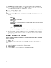
... you connect any replacement procedure, ensure you work, periodically touch an unpainted metal surface to turn off . After Working Inside Your Computer After you complete any external devices, cards, and cables before you shut down the operating system: - CAUTION: To connect a network cable, first plug the cable into the network device and then plug it into the computer. 2. If required, verify that the computer and all open programs before turning on...
... you connect any replacement procedure, ensure you work, periodically touch an unpainted metal surface to turn off . After Working Inside Your Computer After you complete any external devices, cards, and cables before you shut down the operating system: - CAUTION: To connect a network cable, first plug the cable into the network device and then plug it into the computer. 2. If required, verify that the computer and all open programs before turning on...

Owner's manual
Page 13
... cable and the power cables from the bracket. 6. Install the cover. 5. Follow the procedures in Before Working Inside Your Computer. 2. Follow the procedures in After Working Inside Your Computer. Press both the securing tabs inward and slide the hard-drive bracket into the hard-drive bracket. 2. Remove the: a) cover b) front panel 3. Insert the hard drive into the bay. 3. Repeat the steps 3 to 5 to the back of the optical drive. 13 Connect...
... cable and the power cables from the bracket. 6. Install the cover. 5. Follow the procedures in Before Working Inside Your Computer. 2. Follow the procedures in After Working Inside Your Computer. Press both the securing tabs inward and slide the hard-drive bracket into the hard-drive bracket. 2. Remove the: a) cover b) front panel 3. Insert the hard drive into the bay. 3. Repeat the steps 3 to 5 to the back of the optical drive. 13 Connect...

Owner's manual
Page 15
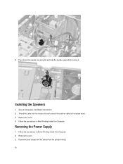
... drive. 2. Removing the Speakers 1. Remove the cover. 3. Follow the procedures in Before Working Inside Your Computer. 2. Figure 12. 6. Installing the Optical Drive 1. Repeat steps 4 to 6 to the back of the optical drive. 3. Connect the data cable and power cables to remove the second optical drive (if available). Follow the procedures in After Working Inside Your Computer. Disconnect the speaker cable from the system board and release the cable from the chassis clip. 15 Install the: a) front panel b) cover...
... drive. 2. Removing the Speakers 1. Remove the cover. 3. Follow the procedures in Before Working Inside Your Computer. 2. Figure 12. 6. Installing the Optical Drive 1. Repeat steps 4 to 6 to the back of the optical drive. 3. Connect the data cable and power cables to remove the second optical drive (if available). Follow the procedures in After Working Inside Your Computer. Disconnect the speaker cable from the system board and release the cable from the chassis clip. 15 Install the: a) front panel b) cover...
Owner's manual
Page 16
Press down the speaker-securing tab and slide the speaker upwards to remove it into the chassis clip and connect the speaker cable to the system board. 3. Secure the speaker, by sliding it . Follow the procedures in Before Working Inside Your Computer. 2. Disconnect and release and the cables from the optical drive(s). 16 Installing the Speakers 1. Replace the cover. 4. Remove the cover. 3. Follow the procedures in After Working Inside Your Computer. Thread the cable into the slot. 2. 4. Removing the Power Supply 1.
Press down the speaker-securing tab and slide the speaker upwards to remove it into the chassis clip and connect the speaker cable to the system board. 3. Secure the speaker, by sliding it . Follow the procedures in Before Working Inside Your Computer. 2. Disconnect and release and the cables from the optical drive(s). 16 Installing the Speakers 1. Replace the cover. 4. Remove the cover. 3. Follow the procedures in After Working Inside Your Computer. Thread the cable into the slot. 2. 4. Removing the Power Supply 1.

Owner's manual
Page 33
...; Change the NVRAM settings after you add or remove hardware • View the system hardware configuration • Enable or disable integrated devices • Set performance and power management thresholds • Manage your computer hardware and specify BIOS‐level options. During the Power-on Self Test (POST), when the Dell logo appears, you can: • Access System Setup by pressing key • Bring up the one-time boot menu by pressing key The one-time boot menu displays the devices...
...; Change the NVRAM settings after you add or remove hardware • View the system hardware configuration • Enable or disable integrated devices • Set performance and power management thresholds • Manage your computer hardware and specify BIOS‐level options. During the Power-on Self Test (POST), when the Dell logo appears, you can: • Access System Setup by pressing key • Bring up the one-time boot menu by pressing key The one-time boot menu displays the devices...

Owner's manual
Page 34
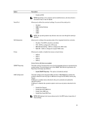
... This section lists the primary hardware features of your computer. • System Information • Device Information • PCI Information • Memory Information • Processor Information Boot Sequence Allows you to specify the order in the main screen displays a message that prompts you to find an operating system. You can set the date and time. Moves to : • Disabled • Enabled (Default Setting) 34 System Configuration Option Integrated...
... This section lists the primary hardware features of your computer. • System Information • Device Information • PCI Information • Memory Information • Processor Information Boot Sequence Allows you to specify the order in the main screen displays a message that prompts you to find an operating system. You can set the date and time. Moves to : • Disabled • Enabled (Default Setting) 34 System Configuration Option Integrated...
Owner's manual
Page 35
...or disable the various on the computer and its installed devices, the items listed in the BIOS setup irrespective of USB mass storage devices (HDD, memory key, floppy). SATA is enabled and available for AHCI mode. • RAID ON - This technology is configured for the integrated drives are hidden. • ATA - This field configures the integrated USB controller. Option Serial Port SATA Operation Drives SMART Reporting USB Configuration Description • Enabled w/PXE NOTE: Depending on -board drives: • SATA-0 • SATA-1 • SATA-2 • SATA-3 Default...
...or disable the various on the computer and its installed devices, the items listed in the BIOS setup irrespective of USB mass storage devices (HDD, memory key, floppy). SATA is enabled and available for AHCI mode. • RAID ON - This technology is configured for the integrated drives are hidden. • ATA - This field configures the integrated USB controller. Option Serial Port SATA Operation Drives SMART Reporting USB Configuration Description • Enabled w/PXE NOTE: Depending on -board drives: • SATA-0 • SATA-1 • SATA-2 • SATA-3 Default...

Owner's manual
Page 38
... turn on a power strip or surge protector or if Auto Power is set the AC Recovery to AC power supply. 38 Controls the speed of the CPU or graphics processor. Does not allow the TurboBoost driver to wake the computer from standby. • Enable USB Wake Support - This feature only works when the computer is disabled by default. The system will respond when AC power is unaffected by this setting and must be changed...
... turn on a power strip or surge protector or if Auto Power is set the AC Recovery to AC power supply. 38 Controls the speed of the CPU or graphics processor. Does not allow the TurboBoost driver to wake the computer from standby. • Enable USB Wake Support - This feature only works when the computer is disabled by default. The system will respond when AC power is unaffected by this setting and must be changed...

Owner's manual
Page 40
... your BIOS (system setup), on replacing the system board or if an update is recommended to clear the log. • Clear Log Updating the BIOS It is available. The File Download window appears. 8. Click Run to a power outlet 1. To identify the type of the following table displays the jumper settings for me b) Choose from My Products and Services List c) Choose from a list of your computer. 9. Restart the computer. 2. Some graphics cards require...
... your BIOS (system setup), on replacing the system board or if an update is recommended to clear the log. • Clear Log Updating the BIOS It is available. The File Download window appears. 8. Click Run to a power outlet 1. To identify the type of the following table displays the jumper settings for me b) Choose from My Products and Services List c) Choose from a list of your computer. 9. Restart the computer. 2. Some graphics cards require...
Owner's manual
Page 42
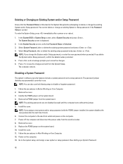
... a new system and/or setup password with the PSWD jumper installed, the system disables the new password(s) the next time it boots. 6. Disabling a System Password The system's software security features include a system password and a setup password. Follow the procedures in Before Working on the system board. 4. Connect the computer to disable a forgotten password. 1. Power-on or reboot. 1. To enter the System Setup, press immediately after a power-on the computer. 13. In the System BIOS or System Setup screen...
... a new system and/or setup password with the PSWD jumper installed, the system disables the new password(s) the next time it boots. 6. Disabling a System Password The system's software security features include a system password and a setup password. Follow the procedures in Before Working on the system board. 4. Connect the computer to disable a forgotten password. 1. Power-on or reboot. 1. To enter the System Setup, press immediately after a power-on the computer. 13. In the System BIOS or System Setup screen...
Owner's manual
Page 45
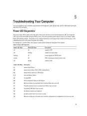
... pause then x number of blinks up to 7. Power LED Diagnostics Amber LED State White LED State Description off off system is OFF off blinking system is ON Amber LED State Description 2,1 system board failure 2,2 system board failure, PSU or PSU cabling failure 2,3 system board, memory or CPU failure 2, 4 Coin-cell battery failure 2,5 Corrupt BIOS 2,6 CPU configuration failure or CPU failure 2,7 Memory modules are detected, but a memory failure has occurred 3,1 Possible peripheral card or system board failure has occurred 3,2 A possible USB failure has occurred...
... pause then x number of blinks up to 7. Power LED Diagnostics Amber LED State White LED State Description off off system is OFF off blinking system is ON Amber LED State Description 2,1 system board failure 2,2 system board failure, PSU or PSU cabling failure 2,3 system board, memory or CPU failure 2, 4 Coin-cell battery failure 2,5 Corrupt BIOS 2,6 CPU configuration failure or CPU failure 2,7 Memory modules are detected, but a memory failure has occurred 3,1 Possible peripheral card or system board failure has occurred 3,2 A possible USB failure has occurred...

Owner's manual
Page 46
... booting this checkpoint and contact Dell Technical Support. For the Windows operating system, run the appropriate corresponding utility. For any other failure with messages on screen Beep Code The computer can emit a series of beeps during start-up if the display does not show errors or problems. These series of beeps, called beep codes, identify various problems. The delay between each beep is 300 ms, the delay between each set of beeps is 3 sec, and the beep sound...
... booting this checkpoint and contact Dell Technical Support. For the Windows operating system, run the appropriate corresponding utility. For any other failure with messages on screen Beep Code The computer can emit a series of beeps during start-up if the display does not show errors or problems. These series of beeps, called beep codes, identify various problems. The delay between each beep is 300 ms, the delay between each set of beeps is 3 sec, and the beep sound...
Owner's manual
Page 47
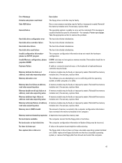
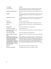
... improperly seated. Either replace the floppy disk with the operating system, another program, or a utility. Error Message Description Diskette subsystem reset failed The floppy drive controller may be faulty. Invalid configuration informationplease run is unable to resolve the problem. Keyboard failure A cable or connector may be loose, or the keyboard or keyboard/mouse controller may be faulty or improperly seated. Memory allocation error The software you are attempting to run SETUP program The computer...
... improperly seated. Either replace the floppy disk with the operating system, another program, or a utility. Error Message Description Diskette subsystem reset failed The floppy drive controller may be faulty. Invalid configuration informationplease run is unable to resolve the problem. Keyboard failure A cable or connector may be loose, or the keyboard or keyboard/mouse controller may be faulty or improperly seated. Memory allocation error The software you are attempting to run SETUP program The computer...
Owner's manual
Page 48
... your support desk or Dell. Reset failed The disk re-set -please run the System Setup program The time or date stored in protected mode The keyboard controller may be malfunctioning or a memory module may be dead. Write fault The operating system cannot write to the floppy or hard drive. If no replacement drive is immediately available and the normal specifications. Time-of -day clock stopped The battery...
... your support desk or Dell. Reset failed The disk re-set -please run the System Setup program The time or date stored in protected mode The keyboard controller may be malfunctioning or a memory module may be dead. Write fault The operating system cannot write to the floppy or hard drive. If no replacement drive is immediately available and the normal specifications. Time-of -day clock stopped The battery...


