
Mobile Precision Re-Image Guide
Page 7
... o Intel® Responsiveness Technologies - Latitude E-Family & Mobile Precision 1st &2nd generation o WiDi display - Latitude E-Family & Mobile Precision 4th generation Reader, Flash, and ARM - Latitude E-Family & Mobile Precision 4th generation o Dell Battery Management - Dell Latitude Ultrabook, E-Family & Mobile Precision Reimage "How-To" Guide o Dell Data Protection | Encryption(DDPE) - Latitude E-Family & Mobile Precision 3rd & 4th generation o Privacy Panel o Touch Screen Digitizer...
... o Intel® Responsiveness Technologies - Latitude E-Family & Mobile Precision 1st &2nd generation o WiDi display - Latitude E-Family & Mobile Precision 4th generation Reader, Flash, and ARM - Latitude E-Family & Mobile Precision 4th generation o Dell Battery Management - Dell Latitude Ultrabook, E-Family & Mobile Precision Reimage "How-To" Guide o Dell Data Protection | Encryption(DDPE) - Latitude E-Family & Mobile Precision 3rd & 4th generation o Privacy Panel o Touch Screen Digitizer...
Mobile Precision Re-Image Guide
Page 11
...4th generations Latitude E-Family & Mobile Precision o Dell Data Protection | Access - 3rd & 4th generations Latitude E-Family & Mobile Precision o Dell Data Protection | Encryption - 3rd & 4th generations Latitude E-Family & Mobile Precision o Latitude On / Precision On - Intel® Smart Connect Technology o Dell Premier Color application, 3rd & 4th generation Latitude Mobile Precision Control Point Connection Manager 3. Communication ...-band communication for System Manager version 1.0 & 1.1 only) DCP - Control Point System Manager DCP Extended Battery Life -
...4th generations Latitude E-Family & Mobile Precision o Dell Data Protection | Access - 3rd & 4th generations Latitude E-Family & Mobile Precision o Dell Data Protection | Encryption - 3rd & 4th generations Latitude E-Family & Mobile Precision o Latitude On / Precision On - Intel® Smart Connect Technology o Dell Premier Color application, 3rd & 4th generation Latitude Mobile Precision Control Point Connection Manager 3. Communication ...-band communication for System Manager version 1.0 & 1.1 only) DCP - Control Point System Manager DCP Extended Battery Life -
Mobile Precision Re-Image Guide
Page 12
...which offers faster performance, eSATA support, and increased battery life. Some of the BIOS settings are critical to support IRRT (Intel's Rapid Recovery Technology). This mode requires an additional storage driver provided by Dell. RAID allows data backup and restoration. See section ... provided by Dell RAID, SATA bus is posted on Dell's driver & downloads support web site (support.dell.com) under the "BIOS" section. IRRT allows data backup and restoration. Dell Latitude Ultrabook, E-Family & Mobile Precision Reimage "How-To" Guide 2.5 BIOS Dell recommends flashing ...
...which offers faster performance, eSATA support, and increased battery life. Some of the BIOS settings are critical to support IRRT (Intel's Rapid Recovery Technology). This mode requires an additional storage driver provided by Dell. RAID allows data backup and restoration. See section ... provided by Dell RAID, SATA bus is posted on Dell's driver & downloads support web site (support.dell.com) under the "BIOS" section. IRRT allows data backup and restoration. Dell Latitude Ultrabook, E-Family & Mobile Precision Reimage "How-To" Guide 2.5 BIOS Dell recommends flashing ...
Mobile Precision Re-Image Guide
Page 20
...Precision Reimage "How-To" Guide 3. Authentec Fingerprint Reader 9. Broadcom Unified Security Hub 10. Dell Smart Card Keyboard 7. Refer to Table B1 under Microsoft Windows Vista only STMicroelectronics Trusted Platform Module 4. Winbond Trusted Platform Module 5. UPEK TouchChip Fingerprint Reader 8. For Extended Battery Life feature (EBL), install the Dell...and beyond) o For Ambient Light Sensor (ALS), install the Dell Ambient Light Sensor Utility component of power management configuring and alerting capabilities: o Battery Status o Power Scheme and Sleep Mode o Display and Devices ...
...Precision Reimage "How-To" Guide 3. Authentec Fingerprint Reader 9. Broadcom Unified Security Hub 10. Dell Smart Card Keyboard 7. Refer to Table B1 under Microsoft Windows Vista only STMicroelectronics Trusted Platform Module 4. Winbond Trusted Platform Module 5. UPEK TouchChip Fingerprint Reader 8. For Extended Battery Life feature (EBL), install the Dell...and beyond) o For Ambient Light Sensor (ALS), install the Dell Ambient Light Sensor Utility component of power management configuring and alerting capabilities: o Battery Status o Power Scheme and Sleep Mode o Display and Devices ...
Mobile Precision Re-Image Guide
Page 22
... Ultrabook, E-Family & Mobile Precision Reimage "How-To" Guide 2.6.10 Dell Feature Enhancement Pack - The Dell Date Protection | Access Application components are required in order: Prerequisites Installer - Both of power management configuring and alerting capabilities Support for hot keys and system events Dell customized power plans and extensions Battery Health Information ...
... Ultrabook, E-Family & Mobile Precision Reimage "How-To" Guide 2.6.10 Dell Feature Enhancement Pack - The Dell Date Protection | Access Application components are required in order: Prerequisites Installer - Both of power management configuring and alerting capabilities Support for hot keys and system events Dell customized power plans and extensions Battery Health Information ...
Mobile Precision Re-Image Guide
Page 40
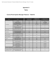
... and sound levels) Digidesign Audio/Video mode Inactivate display and system timeouts when activating an external display using FnF8. Dell Latitude Ultrabook, E-Family & Mobile Precision Reimage "How-To" Guide Appendix D Tables - N/A N/A N/A N/A Yes (Intel LOM) Availabilty of Feature when...Key customizaton Keyboard backlighting Brightness ALS Feature user profiles View battery manufacturer info. battery charge enable/disable status Network card power management Extended Battery Life/ All Day Battery Life. (ADBL) Dell Enhanced Performance Plans (User Selectable Thermal Tables for NTSC, ...
... and sound levels) Digidesign Audio/Video mode Inactivate display and system timeouts when activating an external display using FnF8. Dell Latitude Ultrabook, E-Family & Mobile Precision Reimage "How-To" Guide Appendix D Tables - N/A N/A N/A N/A Yes (Intel LOM) Availabilty of Feature when...Key customizaton Keyboard backlighting Brightness ALS Feature user profiles View battery manufacturer info. battery charge enable/disable status Network card power management Extended Battery Life/ All Day Battery Life. (ADBL) Dell Enhanced Performance Plans (User Selectable Thermal Tables for NTSC, ...
Important Information - Pen
Page 1
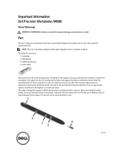
...to help distinguish the two types. The nibs are of different colors to transmit an electric field. pen/stylus 2. It depends on the battery power. The Stylus kit consists of conductive lines on -board processor. The signal from the coil is designed to support multiple pen tip ...the vertical and horizontal conductors. The accurate stylus position is sensed by the excitation coil built into the computer's chassis. Important Information Dell Precision Workstation M6600 About Warnings WARNING: A WARNING indicates a potential for use in tip/screen interaction when writing.
...to help distinguish the two types. The nibs are of different colors to transmit an electric field. pen/stylus 2. It depends on the battery power. The Stylus kit consists of conductive lines on -board processor. The signal from the coil is designed to support multiple pen tip ...the vertical and horizontal conductors. The accurate stylus position is sensed by the excitation coil built into the computer's chassis. Important Information Dell Precision Workstation M6600 About Warnings WARNING: A WARNING indicates a potential for use in tip/screen interaction when writing.
Important Information - Pen
Page 2
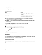
...head. To remove/insert the battery, loosen the screw cap. 1. left click on a mouse or pressing this button activate the field or option. Replacing the pen tip, resolves the problem with '+' sign must be replaced. Install a new pen tip on specific Dell computers. Pen Usage Your computer...click pen button 4. eraser pen button 3. Buttons on hard surfaces. NOTE: If there is designed to replace the battery Table 1. Do not use the pen. 2 Removing/Inserting the Stylus Battery and Pen Tip 1. Holding the pen near the display makes a small cursor appear. To remove the pen tip, ...
...head. To remove/insert the battery, loosen the screw cap. 1. left click on a mouse or pressing this button activate the field or option. Replacing the pen tip, resolves the problem with '+' sign must be replaced. Install a new pen tip on specific Dell computers. Pen Usage Your computer...click pen button 4. eraser pen button 3. Buttons on hard surfaces. NOTE: If there is designed to replace the battery Table 1. Do not use the pen. 2 Removing/Inserting the Stylus Battery and Pen Tip 1. Holding the pen near the display makes a small cursor appear. To remove the pen tip, ...
Owner's Manual
Page 3
... Secure Digital (SD) Card 13 Installing The Secure Digital (SD) Card 13 3 ExpressCard 15 Removing the ExpressCard 15 Installing The ExpressCard 15 4 Battery...17 Removing The Battery...17 Installing The Battery...17 5 Subscriber Identity Module (SIM) Card 19 Removing The Subscriber Identity Module (SIM )Card 19 Installing The Subscriber Identity Module (SIM )Card...
... Secure Digital (SD) Card 13 Installing The Secure Digital (SD) Card 13 3 ExpressCard 15 Removing the ExpressCard 15 Installing The ExpressCard 15 4 Battery...17 Removing The Battery...17 Installing The Battery...17 5 Subscriber Identity Module (SIM) Card 19 Removing The Subscriber Identity Module (SIM )Card 19 Installing The Subscriber Identity Module (SIM )Card...
Owner's Manual
Page 5
... Secondary Memory 46 17 CPU Fan...47 Removing The CPU Fan 47 Installing The CPU Fan...48 18 Coin-Cell Battery 49 Removing The Coin-Cell Battery 49 Installing The Coin-Cell Battery 50 19 Palm Rest 51 Removing The Palm Rest 51 Installing The Palm Rest 56 20 CPU and Heatsink 57...
... Secondary Memory 46 17 CPU Fan...47 Removing The CPU Fan 47 Installing The CPU Fan...48 18 Coin-Cell Battery 49 Removing The Coin-Cell Battery 49 Installing The Coin-Cell Battery 50 19 Palm Rest 51 Removing The Palm Rest 51 Installing The Palm Rest 56 20 CPU and Heatsink 57...

Owner's Manual
Page 7
... 111 37 System Setup 117 System Setup Overview 117 Entering System Setup 117 System Setup Menu Options 117 38 Diagnostics 131 Device Status Lights...131 Battery Status Lights...131 Diagnostics...131 39 Contacting Dell 135 Contacting Dell ...135
... 111 37 System Setup 117 System Setup Overview 117 Entering System Setup 117 System Setup Menu Options 117 38 Diagnostics 131 Device Status Lights...131 Battery Status Lights...131 Diagnostics...131 39 Contacting Dell 135 Contacting Dell ...135
Owner's Manual
Page 10
...computer, ground yourself by touching an unpainted metal surface, such as the optional Media Base or Battery Slice, undock it. NOTE: To avoid damaging the system board, you must remove the main battery before you begin working inside your computer and then unplug the cable from the computer. 5. ...docking device (docked) such as the metal at the back of your computer and all network cables from the network device. 4. Remove the main battery (see Turning Off Your Computer). 3. Open the display. 10. Ensure that your work surface is connected to prevent the computer cover from the ...
...computer, ground yourself by touching an unpainted metal surface, such as the optional Media Base or Battery Slice, undock it. NOTE: To avoid damaging the system board, you must remove the main battery before you begin working inside your computer and then unplug the cable from the computer. 5. ...docking device (docked) such as the metal at the back of your computer and all network cables from the network device. 4. Remove the main battery (see Turning Off Your Computer). 3. Open the display. 10. Ensure that your work surface is connected to prevent the computer cover from the ...

Owner's Manual
Page 11
...button for about 4 seconds to turn off your computer. 1. Connect any external devices, such as a port replicator, battery slice, or media base, and replace any cards, such as shown below, and then click Shut Down. •... In Windows XP: Click Start → Turn Off Computer → Turn Off . Do not use only the battery designed for other Dell computers. 1. • #0 Phillips screwdriver • #1 Phillips screwdriver • Small plastic scribe • Flash BIOS ...any telephone or network cables to the computer, use batteries designed for this particular Dell computer.
...button for about 4 seconds to turn off your computer. 1. Connect any external devices, such as a port replicator, battery slice, or media base, and replace any cards, such as shown below, and then click Shut Down. •... In Windows XP: Click Start → Turn Off Computer → Turn Off . Do not use only the battery designed for other Dell computers. 1. • #0 Phillips screwdriver • #1 Phillips screwdriver • Small plastic scribe • Flash BIOS ...any telephone or network cables to the computer, use batteries designed for this particular Dell computer.

Owner's Manual
Page 12
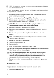
CAUTION: To connect a network cable, first plug the cable into the network device and then plug it into the computer. 3. Replace the battery. 4. Turn on your computer and all attached devices to their electrical outlets. 5. Connect your computer. 12
CAUTION: To connect a network cable, first plug the cable into the network device and then plug it into the computer. 3. Replace the battery. 4. Turn on your computer and all attached devices to their electrical outlets. 5. Connect your computer. 12

Owner's Manual
Page 17
Remove the battery from the computer. Slide the battery release latch into the computer. 2. Installing The Battery 1. Battery 4 Removing The Battery 1. Follow the procedures in After Working Inside Your Computer. 17 Slide the battery back into the unlock position. 3. The battery release latch automatically clicks back to the locked position. 3. Follow the procedures in Before Working On Your Computer. 2.
Remove the battery from the computer. Slide the battery release latch into the computer. 2. Installing The Battery 1. Battery 4 Removing The Battery 1. Follow the procedures in After Working Inside Your Computer. 17 Slide the battery back into the unlock position. 3. The battery release latch automatically clicks back to the locked position. 3. Follow the procedures in Before Working On Your Computer. 2.
Owner's Manual
Page 19
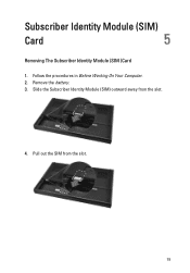
Remove the battery. 3. Slide the Subscriber Identity Module (SIM) outward away from the slot. 19 Pull out the SIM from the slot. 4. Follow the procedures in Before Working On Your Computer. 2. Subscriber Identity Module (SIM) Card 5 Removing The Subscriber Identity Module (SIM )Card 1.
Remove the battery. 3. Slide the Subscriber Identity Module (SIM) outward away from the slot. 19 Pull out the SIM from the slot. 4. Follow the procedures in Before Working On Your Computer. 2. Subscriber Identity Module (SIM) Card 5 Removing The Subscriber Identity Module (SIM )Card 1.

Owner's Manual
Page 20
Follow the procedures in the battery compartment. 2. Locate the Subscriber Identity Module (SIM) card slot in After Working Inside Your Computer. 20 Replace the battery. 4. Push the SIM card into the slot until it is fully engaged. 3. Installing The Subscriber Identity Module (SIM )Card 1.
Follow the procedures in the battery compartment. 2. Locate the Subscriber Identity Module (SIM) card slot in After Working Inside Your Computer. 20 Replace the battery. 4. Push the SIM card into the slot until it is fully engaged. 3. Installing The Subscriber Identity Module (SIM )Card 1.
Owner's Manual
Page 21
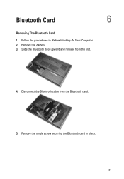
Bluetooth Card 6 Removing The Bluetooth Card 1. Remove the single screw securing the Bluetooth card in Before Working On Your Computer 2. Follow the procedures in place. 21 Disconnect the Bluetooth cable from the slot. 4. Remove the battery. 3. Slide the Bluetooth door upward and release from the Bluetooth card. 5.
Bluetooth Card 6 Removing The Bluetooth Card 1. Remove the single screw securing the Bluetooth card in Before Working On Your Computer 2. Follow the procedures in place. 21 Disconnect the Bluetooth cable from the slot. 4. Remove the battery. 3. Slide the Bluetooth door upward and release from the Bluetooth card. 5.
Owner's Manual
Page 22
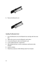
Installing The Bluetooth Card 1. Tighten the screw to the Bluetooth card. 4. Slide the Bluetooth door onto the compartment until the tab is fully engaged. 6. Install the battery. 7. Locate the Bluetooth door compartment. 5. Follow the procedures in place. 3. Place the Bluetooth card on the Bluetooth door and align with the screw hole. 2. 6. Connect the Bluetooth cable to secure the Bluetooth card in After Working Inside Your Computer. 22 Remove the Bluetooth card.
Installing The Bluetooth Card 1. Tighten the screw to the Bluetooth card. 4. Slide the Bluetooth door onto the compartment until the tab is fully engaged. 6. Install the battery. 7. Locate the Bluetooth door compartment. 5. Follow the procedures in place. 3. Place the Bluetooth card on the Bluetooth door and align with the screw hole. 2. 6. Connect the Bluetooth cable to secure the Bluetooth card in After Working Inside Your Computer. 22 Remove the Bluetooth card.
Owner's Manual
Page 23
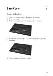
Press the rubber feet towards the rear of the computer to the computer. 4. Base Cover 7 Removing The Base Cover 1. Remove the battery. 3. Remove the screws that secure the base cover to disengage the bottom door. 5. Remove the base cover from the computer. 23 Follow the procedures in Before Working On Your Computer. 2.
Press the rubber feet towards the rear of the computer to the computer. 4. Base Cover 7 Removing The Base Cover 1. Remove the battery. 3. Remove the screws that secure the base cover to disengage the bottom door. 5. Remove the base cover from the computer. 23 Follow the procedures in Before Working On Your Computer. 2.

