Quick Reference Guide
Page 21
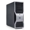
Inside View 1 2 7 6 1 2 3 4 5 6 7 3 5 4 power supply hard drive bay memory shroud NOTICE: The memory shroud holds the (optional) memory riser cards in order to secure the risers and to avoid damage. front fan card fan 5.25-inch drive bay with 3.5-inch drive panel plate 5.25-inch drive bay Quick Reference Guide 21 its thumbscrews must be sufficiently tight in place;
Inside View 1 2 7 6 1 2 3 4 5 6 7 3 5 4 power supply hard drive bay memory shroud NOTICE: The memory shroud holds the (optional) memory riser cards in order to secure the risers and to avoid damage. front fan card fan 5.25-inch drive bay with 3.5-inch drive panel plate 5.25-inch drive bay Quick Reference Guide 21 its thumbscrews must be sufficiently tight in place;

Quick Reference Guide
Page 23
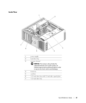
...-graphics configuration, this slot is replaced by a x16 slot on the graphics riser. It holds a graphics card. 30 memory fan connector (FAN_MEM) 31 white memory module connectors (DIMM_1-4) support memory modules or memory module risers 32 black memory module connectors (DIMM_5-8) support memory modules only when no memory riser cards are installed; It holds a graphic card. 28 PCI-Express x16...
...-graphics configuration, this slot is replaced by a x16 slot on the graphics riser. It holds a graphics card. 30 memory fan connector (FAN_MEM) 31 white memory module connectors (DIMM_1-4) support memory modules or memory module risers 32 black memory module connectors (DIMM_5-8) support memory modules only when no memory riser cards are installed; It holds a graphic card. 28 PCI-Express x16...
Quick Reference Guide
Page 36
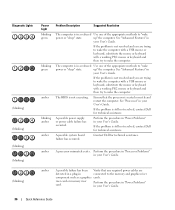
... A possible power supply or power cable failure has occurred. amber A possible failure has been Verify that the processor is still not resolved, contact Dell for technical assistance. riser card or memory riser card. See "Advanced Features" in your User's Guide. See "Processor" in your User's Guide. A possible system board failure has occurred. Diagnostic Lights...to wake the computer with a USB mouse or keyboard, substitute the mouse or keyboard with a working PS/2 mouse or keyboard and then try to the memory and graphics riser component such as a graphics cards.
... A possible power supply or power cable failure has occurred. amber A possible failure has been Verify that the processor is still not resolved, contact Dell for technical assistance. riser card or memory riser card. See "Advanced Features" in your User's Guide. See "Processor" in your User's Guide. A possible system board failure has occurred. Diagnostic Lights...to wake the computer with a USB mouse or keyboard, substitute the mouse or keyboard with a working PS/2 mouse or keyboard and then try to the memory and graphics riser component such as a graphics cards.
User Guide
Page 5
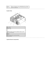
Inside View 1 power supply 2 hard drive bay 3 memory shroud NOTICE: The memory shroud holds the (optional) memory riser cards in order to secure the risers and to the serial port. If necessary, the address for this port can be sufficiently tight in place; its thumbscrews must be modified through system setup (see System Setup). 13 serial connector Connect a serial device, such as a handheld device, to avoid damage. 4 front fan 5 card fan 6 5.25-inch drive bay with 3.5-inch drive panel plate 7 5.25-inch drive bay System Board Components
Inside View 1 power supply 2 hard drive bay 3 memory shroud NOTICE: The memory shroud holds the (optional) memory riser cards in order to secure the risers and to the serial port. If necessary, the address for this port can be sufficiently tight in place; its thumbscrews must be modified through system setup (see System Setup). 13 serial connector Connect a serial device, such as a handheld device, to avoid damage. 4 front fan 5 card fan 6 5.25-inch drive bay with 3.5-inch drive panel plate 7 5.25-inch drive bay System Board Components

User Guide
Page 7
... card. 31 memory fan connector (FAN_MEM) 32 white memory module connectors (DIMM_14) support memory modules or memory module risers 33 black memory module connectors (DIMM_5-8) support memory modules only when no memory riser cards are installed; otherwise these must be left empty 34 primary processor connector (CPU_0) Cable Colors Device Hard drive (with on the graphics riser. 13 main power...
... card. 31 memory fan connector (FAN_MEM) 32 white memory module connectors (DIMM_14) support memory modules or memory module risers 33 black memory module connectors (DIMM_5-8) support memory modules only when no memory riser cards are installed; otherwise these must be left empty 34 primary processor connector (CPU_0) Cable Colors Device Hard drive (with on the graphics riser. 13 main power...
User Guide
Page 44
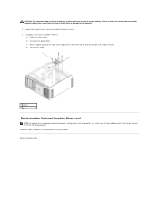
CAUTION: The computer stand should be ordered from Dell. b. c. See Contacting Dell. Follow the steps for graphics riser card removal in bodily injury or damage to install the stand could result in the computer tipping over, potentially resulting ...or downgrade from the card fan and the memory-riser support structure. Remove its power cable. Disconnect its four screws. Set the riser aside. 1 screws 2 graphics riser card Replacing the Optional Graphics Riser Card NOTE: To upgrade to ensure maximum system stability. If a graphics riser card is installed, remove it from a ...
CAUTION: The computer stand should be ordered from Dell. b. c. See Contacting Dell. Follow the steps for graphics riser card removal in bodily injury or damage to install the stand could result in the computer tipping over, potentially resulting ...or downgrade from the card fan and the memory-riser support structure. Remove its power cable. Disconnect its four screws. Set the riser aside. 1 screws 2 graphics riser card Replacing the Optional Graphics Riser Card NOTE: To upgrade to ensure maximum system stability. If a graphics riser card is installed, remove it from a ...
User Guide
Page 49
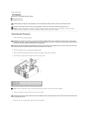
... the computer tipping over while lifting. See your computer from the computer. 4. Lift the memory fan away from the computer. Back to Contents Page Processor Dell Precision™ Workstation 690 User's Guide Removing the Processor Installing the Processor CAUTION: Before you begin any of your computer...safety instructions in bodily injury or damage to the computer. 2. Failure to access the heatsink screws. 1 memory shroud 2 thumbscrews (2) 3 memory fan (only present on computers without memory riser cards) NOTE: To loosen the two captive screws on each side of 55 lbs) and can do so...
... the computer tipping over while lifting. See your computer from the computer. 4. Lift the memory fan away from the computer. Back to Contents Page Processor Dell Precision™ Workstation 690 User's Guide Removing the Processor Installing the Processor CAUTION: Before you begin any of your computer...safety instructions in bodily injury or damage to the computer. 2. Failure to access the heatsink screws. 1 memory shroud 2 thumbscrews (2) 3 memory fan (only present on computers without memory riser cards) NOTE: To loosen the two captive screws on each side of 55 lbs) and can do so...

User Guide
Page 50
... lever from Dell, reuse the original heat-sink assembly when you install your new processor. 7. If you are not installing a processor upgrade kit from under the center cover latch on the pins in order to secure the risers and to fall on the socket. NOTICE: The memory shroud holds the (optional) memory risers in the...
... lever from Dell, reuse the original heat-sink assembly when you install your new processor. 7. If you are not installing a processor upgrade kit from under the center cover latch on the pins in order to secure the risers and to fall on the socket. NOTICE: The memory shroud holds the (optional) memory risers in the...

User Guide
Page 51
...installed at all times to ensure maximum system stability. See your Product Information Guide for other important safety information. Ensure that secure the memory shroud and lift it away from under the center cover latch on the socket. Installing the Processor NOTICE: Ground yourself by sliding ...only present on the computer. 6. Loosen the captive thumbscrews that the release lever is heavy (it ; If you turn on systems without memory riser cards) 4. Seek assistance before attempting to lift, move, or tilt it has an approximate minimum weight of the pins inside the socket...
...installed at all times to ensure maximum system stability. See your Product Information Guide for other important safety information. Ensure that secure the memory shroud and lift it away from under the center cover latch on the socket. Installing the Processor NOTICE: Ground yourself by sliding ...only present on the computer. 6. Loosen the captive thumbscrews that the release lever is heavy (it ; If you turn on systems without memory riser cards) 4. Seek assistance before attempting to lift, move, or tilt it has an approximate minimum weight of the pins inside the socket...

User Guide
Page 53
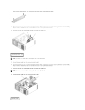
...into the computer. 18. Install the heat-sink assembly: a. its thumbscrews must be sufficiently tight in order to secure the risers and to Dell in the same package in place; Ensure that the new processor has been installed properly. Press to enter system setup and .... 1 heat-sink assembly 2 captive screw housing (4) NOTICE: The memory shroud holds the (optional) memory risers in which your replacement kit was sent. 14. Connect the computer and devices to Contents Page b. Replace the memory shroud and memory fan. Replace the computer cover (see Replacing the Computer Cover). Back...
...into the computer. 18. Install the heat-sink assembly: a. its thumbscrews must be sufficiently tight in order to secure the risers and to Dell in the same package in place; Ensure that the new processor has been installed properly. Press to enter system setup and .... 1 heat-sink assembly 2 captive screw housing (4) NOTICE: The memory shroud holds the (optional) memory risers in which your replacement kit was sent. 14. Connect the computer and devices to Contents Page b. Replace the memory shroud and memory fan. Replace the computer cover (see Replacing the Computer Cover). Back...
User Guide
Page 80
...length heat spreaders (FLHS) are required for any memory in a memory riser and for 667 MHz DIMMs. 32 or 64 GB (with optional memory riser cards) F0000h Intel 5000X 64 bits 36 bits 8 24 8-Mb Integrated network interface with users of Dell Precision™ products and the Linux operating system l ...Additional information regarding Linux and my Dell Precision computer NOTE: The color of 10/100...
...length heat spreaders (FLHS) are required for any memory in a memory riser and for 667 MHz DIMMs. 32 or 64 GB (with optional memory riser cards) F0000h Intel 5000X 64 bits 36 bits 8 24 8-Mb Integrated network interface with users of Dell Precision™ products and the Linux operating system l ...Additional information regarding Linux and my Dell Precision computer NOTE: The color of 10/100...

User Guide
Page 105
... and lift to remove it from the card fan and the memory-riser support structure. If a graphics riser card is in reverse order. Set the riser aside. 5. Remove the mounting screws from the computer. Back to computer problems. 10. Loosen the captive thumbscrews that hold the processor and card fan case ...
... and lift to remove it from the card fan and the memory-riser support structure. If a graphics riser card is in reverse order. Set the riser aside. 5. Remove the mounting screws from the computer. Back to computer problems. 10. Loosen the captive thumbscrews that hold the processor and card fan case ...

User Guide
Page 106
... Memory Dell Precision™ Workstation 690 User's Guide Addressing Memory With 4-GB or Greater Configurations (32-bit Operating Systems Only) Fully Buffered DIMM (FBD) Memory Overview Memory Installation (Without Memory Riser Cards) Installing Memory Without Memory Riser Cards Removing Memory Without Memory Riser Cards Memory Installation (With Optional Memory Riser Cards) Installing Memory (With Optional Memory Riser Cards) Removing Memory (With Optional Memory Riser Cards) Your computer supports fully-buffered ECC DDR2 memory only. Addressing Memory...
... Memory Dell Precision™ Workstation 690 User's Guide Addressing Memory With 4-GB or Greater Configurations (32-bit Operating Systems Only) Fully Buffered DIMM (FBD) Memory Overview Memory Installation (Without Memory Riser Cards) Installing Memory Without Memory Riser Cards Removing Memory Without Memory Riser Cards Memory Installation (With Optional Memory Riser Cards) Installing Memory (With Optional Memory Riser Cards) Removing Memory (With Optional Memory Riser Cards) Your computer supports fully-buffered ECC DDR2 memory only. Addressing Memory...

User Guide
Page 107
...case, the computer will continue to operate, but with full-length heat spreaders 3 information label Memory Installation (Without Memory Riser Cards) Fully buffered DDR2 memory modules can be matched in Before You Begin. Remove the computer cover (see Removing the Computer Cover).... Installing Memory Without Memory Riser Cards CAUTION: Before you touch any of memory should be installed in pairs of your computer from your Product Information Guide for other important safety...
...case, the computer will continue to operate, but with full-length heat spreaders 3 information label Memory Installation (Without Memory Riser Cards) Fully buffered DDR2 memory modules can be matched in Before You Begin. Remove the computer cover (see Removing the Computer Cover).... Installing Memory Without Memory Riser Cards CAUTION: Before you touch any of memory should be installed in pairs of your computer from your Product Information Guide for other important safety...

User Guide
Page 109
...on the fan support structure. 1 memory shroud 2 thumbscrews (2) 3 memory fan NOTICE: The memory shroud holds the (optional) memory risers in order to secure the risers and to avoid damage. 9. If it into position. If the memory total is correct, skip to step 14. 13. Place the memory fan on . 12. Press to...the module. 7. If you apply equal force to verify that they are operating properly. Replace the memory shroud. Replace the computer cover (see Replacing the Computer Cover). Run the Dell Diagnostics to each end of the module. 8. Return to step 1 of this procedure, but instead...
...on the fan support structure. 1 memory shroud 2 thumbscrews (2) 3 memory fan NOTICE: The memory shroud holds the (optional) memory risers in order to secure the risers and to avoid damage. 9. If it into position. If the memory total is correct, skip to step 14. 13. Place the memory fan on . 12. Press to...the module. 7. If you apply equal force to verify that they are operating properly. Replace the memory shroud. Replace the computer cover (see Replacing the Computer Cover). Run the Dell Diagnostics to each end of the module. 8. Return to step 1 of this procedure, but instead...

User Guide
Page 110
...Failure to install the stand could result in the computer tipping over while lifting. Ensure that secure the memory shroud and lift it aside. 1 memory fan 2 memory fan support structure CAUTION: Fully-buffered memory modules may become very hot during normal operation. CAUTION: The computer stand should be difficult to the ... metal surface on the computer. 1. NOTICE: To prevent static damage to avoid injury; Seek assistance before opening the cover. Removing Memory Without Memory Riser Cards CAUTION: Before you begin any of your computer's electronic components.
...Failure to install the stand could result in the computer tipping over while lifting. Ensure that secure the memory shroud and lift it aside. 1 memory fan 2 memory fan support structure CAUTION: Fully-buffered memory modules may become very hot during normal operation. CAUTION: The computer stand should be difficult to the ... metal surface on the computer. 1. NOTICE: To prevent static damage to avoid injury; Seek assistance before opening the cover. Removing Memory Without Memory Riser Cards CAUTION: Before you begin any of your computer's electronic components.

User Guide
Page 111
... thumbscrews must be sufficiently tight in order to remove it into . Memory must be installed on each other. Grasp the module and pull up. Memory Installation (With Optional Memory Riser Cards) NOTICE: The memory shroud holds the (optional) memory risers in order to secure the riser cards and to avoid damage. These numbers indicate which DIMM slot on...
... thumbscrews must be sufficiently tight in order to remove it into . Memory must be installed on each other. Grasp the module and pull up. Memory Installation (With Optional Memory Riser Cards) NOTICE: The memory shroud holds the (optional) memory risers in order to secure the riser cards and to avoid damage. These numbers indicate which DIMM slot on...

User Guide
Page 112
... computer. 1. See your computer from the computer. in sets of four with one of the four on the system board; Install memory modules in Before You Begin. Installing Memory (With Optional Memory Riser Cards) CAUTION: Before you touch them. CAUTION: To guard against electrical shock, always unplug your Product Information Guide for other important...
... computer. 1. See your computer from the computer. in sets of four with one of the four on the system board; Install memory modules in Before You Begin. Installing Memory (With Optional Memory Riser Cards) CAUTION: Before you touch them. CAUTION: To guard against electrical shock, always unplug your Product Information Guide for other important...

User Guide
Page 113
... until the module snaps into the connector while you touch them. 8. Ensure that it from the connector. 1 memory riser cards 1 and 2 2 memory riser cards 3 and 4 6. Align the notch on the system board. Disconnect the power cables from memory riser card 1 and 2. 5. Press out the securing clip at each end of the module with the crossbar in...
... until the module snaps into the connector while you touch them. 8. Ensure that it from the connector. 1 memory riser cards 1 and 2 2 memory riser cards 3 and 4 6. Align the notch on the system board. Disconnect the power cables from memory riser card 1 and 2. 5. Press out the securing clip at each end of the module with the crossbar in...
User Guide
Page 114
... notch on the bottom of each riser card with the crossbar in , the system will not boot. 16. Connect the power cables back into memory riser cards 1 and 2. 1 memory shroud Insert the riser cards into the connectors until both riser cards snap into position. 1 memory riser cards 1 and 2 2 memory riser cards 3 and 4 NOTE: If a memory-riser power cable is not plugged in...
... notch on the bottom of each riser card with the crossbar in , the system will not boot. 16. Connect the power cables back into memory riser cards 1 and 2. 1 memory shroud Insert the riser cards into the connectors until both riser cards snap into position. 1 memory riser cards 1 and 2 2 memory riser cards 3 and 4 NOTE: If a memory-riser power cable is not plugged in...


