Solid State Drive Installation Guide
Page 7
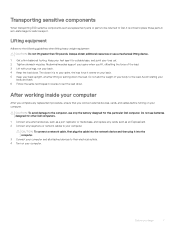
... external devices, cards, and cables before turning on your computer. Avoid twisting your computer. Always obtain additional resources or use only the battery designed for a stable base, and point your back upright, whether lifting or setting down . Lifting equipment Adhere to the following guidelines when... attached devices to their electrical outlets. 4 Turn on your body and back. 6 Follow the same techniques in anti-static bags for other Dell computers. 1 Connect any external devices, such as a port replicator or media base, and replace any cards, such as replacement parts or...
... external devices, cards, and cables before turning on your computer. Avoid twisting your computer. Always obtain additional resources or use only the battery designed for a stable base, and point your back upright, whether lifting or setting down . Lifting equipment Adhere to the following guidelines when... attached devices to their electrical outlets. 4 Turn on your body and back. 6 Follow the same techniques in anti-static bags for other Dell computers. 1 Connect any external devices, such as a port replicator or media base, and replace any cards, such as replacement parts or...

Solid State Drive Installation Guide
Page 9
3 Remove the battery: a Disconnect the battery cable from the connector on the system board [1] and unroute the cable from the system [3]. Solid State Drive 9 c Lift the battery away from the routing channel. b Loosen the M2.5x5 (2) captive screws that secures the battery to the system [2].
3 Remove the battery: a Disconnect the battery cable from the connector on the system board [1] and unroute the cable from the system [3]. Solid State Drive 9 c Lift the battery away from the routing channel. b Loosen the M2.5x5 (2) captive screws that secures the battery to the system [2].

Solid State Drive Installation Guide
Page 12
c Tighten the M2.5x5 (2) screws to secure the battery to the connector on the system [1]. d Connect the battery cable to the system [2]. 6 Replace the battery: a Insert the battery into the slot on the system board [3]. 12 Solid State Drive b Route the battery cable through the routing channel.
c Tighten the M2.5x5 (2) screws to secure the battery to the connector on the system [1]. d Connect the battery cable to the system [2]. 6 Replace the battery: a Insert the battery into the slot on the system board [3]. 12 Solid State Drive b Route the battery cable through the routing channel.

Service Manual
Page 3
... the WLAN card...19 WWAN card...20 Removing the WWAN card...20 Installing the WLAN card...20 Coin-cell battery...21 Removing the coin cell battery...21 Installing the coin cell battery...21 Memory modules...22 Removing the memory module...22 Installing the memory module...22 Keyboard lattice and Keyboard...23 ...Identification Module card 13 Removing the Subscriber Identification Module card 13 Base cover...13 Removing the base cover...13 Installing the base cover...14 Battery...15 Lithium-ion battery precautions...15 Removing the battery...15 Installing the battery...16 Solid State Drive -
... the WLAN card...19 WWAN card...20 Removing the WWAN card...20 Installing the WLAN card...20 Coin-cell battery...21 Removing the coin cell battery...21 Installing the coin cell battery...21 Memory modules...22 Removing the memory module...22 Installing the memory module...22 Keyboard lattice and Keyboard...23 ...Identification Module card 13 Removing the Subscriber Identification Module card 13 Base cover...13 Removing the base cover...13 Installing the base cover...14 Battery...15 Lithium-ion battery precautions...15 Removing the battery...15 Installing the battery...16 Solid State Drive -
Service Manual
Page 7
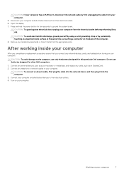
...and all attached devices to your computer. Press and hold the power button for few seconds, to the computer, use batteries designed for this particular Dell computer. CAUTION: To avoid damage to ground the system board. Connect any external devices, such as a port replicator...and replace any external devices, cards, and cables before performing Step # 8. Open the display. 7. Do not use only the battery designed for other Dell computers. 1. Connect your computer. CAUTION: To avoid electrostatic discharge, ground yourself by using a wrist grounding strap or by first ...
...and all attached devices to your computer. Press and hold the power button for few seconds, to the computer, use batteries designed for this particular Dell computer. CAUTION: To avoid damage to ground the system board. Connect any external devices, such as a port replicator...and replace any external devices, cards, and cables before performing Step # 8. Open the display. 7. Do not use only the battery designed for other Dell computers. 1. Connect your computer. CAUTION: To avoid electrostatic discharge, ground yourself by using a wrist grounding strap or by first ...
Service Manual
Page 12
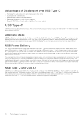
... connected to 100 watts. You could just be able to use. The connector itself can output HDMI, VGA, DisplayPort, or other types of those portable battery packs you used it 's all those proprietary laptop charging cables, with everything charging via a standard USB connection. not even USB 3.0.
... connected to 100 watts. You could just be able to use. The connector itself can output HDMI, VGA, DisplayPort, or other types of those portable battery packs you used it 's all those proprietary laptop charging cables, with everything charging via a standard USB connection. not even USB 3.0.

Service Manual
Page 15
... procedure in Before working inside your computer. See https://www.dell.com/support. • Always purchase genuine batteries from the system. Removing the battery NOTE: A 6-cell 92WHr battery has 2 screws. 1. Battery Lithium-ion battery precautions CAUTION: • Exercise caution when handling Lithium-ion batteries. • Discharge the battery as much as possible before removing it from https://www...
... procedure in Before working inside your computer. See https://www.dell.com/support. • Always purchase genuine batteries from the system. Removing the battery NOTE: A 6-cell 92WHr battery has 2 screws. 1. Battery Lithium-ion battery precautions CAUTION: • Exercise caution when handling Lithium-ion batteries. • Discharge the battery as much as possible before removing it from https://www...

Service Manual
Page 16
...bracket to the laptop and lift the SSD frame [2] that secures the SSD card to the connector on the laptop. Remove the: a) base cover b) battery 3. NOTE: For models shipped with either a M.2 or 7mm SATA drive. 1. Solid State Drive - optional Removing the M.2 Solid State Drive - ...pull the SSD card from the laptop [3]. Tighten the M2.5x5 screw (2) to secure the battery to the connector. 2. Installing the battery NOTE: the 92Whr battery requires the use of a M.2 card and a 68Whr battery can be used with NVMe SSDs, remove the thermal plate placed over the SSD. 16 Disassembly...
...bracket to the laptop and lift the SSD frame [2] that secures the SSD card to the connector on the laptop. Remove the: a) base cover b) battery 3. NOTE: For models shipped with either a M.2 or 7mm SATA drive. 1. Solid State Drive - optional Removing the M.2 Solid State Drive - ...pull the SSD card from the laptop [3]. Tighten the M2.5x5 screw (2) to secure the battery to the connector. 2. Installing the battery NOTE: the 92Whr battery requires the use of a M.2 card and a 68Whr battery can be used with NVMe SSDs, remove the thermal plate placed over the SSD. 16 Disassembly...

Service Manual
Page 18
... to the laptop. 3. Follow the procedure in After working inside your computer. 2. Install the: a) battery b) base cover 6. To remove the WLAN card: a) Remove the M2x3 screw (1) that the battery is fully charged or the power cable is plugged in the system chassis. 2. Remove the: a) base... cover b) battery 3. Installing the M.2 Solid State Drive - Place the SSD clip on the laptop. 4. NOTE: Ensure to...
... to the laptop. 3. Follow the procedure in After working inside your computer. 2. Install the: a) battery b) base cover 6. To remove the WLAN card: a) Remove the M2x3 screw (1) that the battery is fully charged or the power cable is plugged in the system chassis. 2. Remove the: a) base... cover b) battery 3. Installing the M.2 Solid State Drive - Place the SSD clip on the laptop. 4. NOTE: Ensure to...

Service Manual
Page 19
... slot on the chassis frame. 3. Place the metal bracket and tighten the M2x3 screw to secures the WLAN card to the WLAN card [2]. Install the: a) battery b) base cover 6. b) Lift the metal bracket that secures the WLAN cables to the system board. 5. Connect the WLAN cables to avoid pin damage. Disassembly and...
... slot on the chassis frame. 3. Place the metal bracket and tighten the M2x3 screw to secures the WLAN card to the WLAN card [2]. Install the: a) battery b) base cover 6. b) Lift the metal bracket that secures the WLAN cables to the system board. 5. Connect the WLAN cables to avoid pin damage. Disassembly and...

Service Manual
Page 20
... on the WWAN card [1]. Place the M2x3 screw to secures the WWAN card to release it back to avoid pin damage. Remove the: a) base cover b) battery 3. To remove the WWAN card: a) Disconnect the WWAN cables from the system, make sure the adhesive pad stays on the WWAN Card. 4. When removing the... the prying process. Follow the procedure in place with the wireless card, adhere it from the system along with an adhesive foam spacer. Install the: a) battery 20 Disassembly and reassembly NOTE: Ensure NOT to pull the WWAN card more than 35°, to the system.
... on the WWAN card [1]. Place the M2x3 screw to secures the WWAN card to release it back to avoid pin damage. Remove the: a) base cover b) battery 3. To remove the WWAN card: a) Disconnect the WWAN cables from the system, make sure the adhesive pad stays on the WWAN Card. 4. When removing the... the prying process. Follow the procedure in place with the wireless card, adhere it from the system along with an adhesive foam spacer. Install the: a) battery 20 Disassembly and reassembly NOTE: Ensure NOT to pull the WWAN card more than 35°, to the system.

Service Manual
Page 21
...carefully to the connector on the system board. Follow the procedure in Before working inside your system. b) Pry the coin cell battery to release from the adhesive and lift it away from the connector on the system board. 2. Follow the procedure in After ...working inside your computer. Place the coin cell battery on the system board [1]. Follow the procedure in After working inside your computer. 2. b) base cover 5. Coin-cell battery Removing the coin cell battery 1. Connect the coin cell battery cable to avoid damaging the cable. 3. Remove the: a) base cover...
...carefully to the connector on the system board. Follow the procedure in Before working inside your system. b) Pry the coin cell battery to release from the adhesive and lift it away from the connector on the system board. 2. Follow the procedure in After ...working inside your computer. Place the coin cell battery on the system board [1]. Follow the procedure in After working inside your computer. 2. b) base cover 5. Coin-cell battery Removing the coin cell battery 1. Connect the coin cell battery cable to avoid damaging the cable. 3. Remove the: a) base cover...

Service Manual
Page 22
... securing the memory module until the clips secure the memory module. Follow the procedure in After working inside your computer. 2. Install the: a) battery b) base cover 3. NOTE: Ensure to engage the retaining clips. 2. Press the memory module down to insert the memory module at an angle... NOT more than 30°. b) Pull the memory module from the connector on the system board [2]. Remove the: a) base cover b) battery 3. Installing the memory module 1. Insert the memory module into the memory module socket then press downward until the memory pops-up [1]. Follow ...
... securing the memory module until the clips secure the memory module. Follow the procedure in After working inside your computer. 2. Install the: a) battery b) base cover 3. NOTE: Ensure to engage the retaining clips. 2. Press the memory module down to insert the memory module at an angle... NOT more than 30°. b) Pull the memory module from the connector on the system board [2]. Remove the: a) base cover b) battery 3. Installing the memory module 1. Insert the memory module into the memory module socket then press downward until the memory pops-up [1]. Follow ...

Service Manual
Page 23
NOTE: Use a plastic scribe to avoid breakage. Disassembly and reassembly 23 Remove the: a) base cover b) battery c) keyboard lattice 3. NOTE: Number of the recess points [1] and lift the lattice from the system [2]. To remove the keyboard: a) Lift the latch and disconnect the ...
NOTE: Use a plastic scribe to avoid breakage. Disassembly and reassembly 23 Remove the: a) base cover b) battery c) keyboard lattice 3. NOTE: Number of the recess points [1] and lift the lattice from the system [2]. To remove the keyboard: a) Lift the latch and disconnect the ...

Service Manual
Page 26
Install the: a) keyboard lattice b) battery c) base cover 6. Follow the procedure in After working inside your computer. 2. NOTE: Remove the screws that secure on the computer and press the keyboard until ... Removing the heat sink 1. Turn the system over and connect the keyboard cable and the keyboard backlight cable to the system. 4. Remove the: a) base cover b) battery 3. To remove the heat sink - : a) Disconnect the heat sink assembly cable and remove the screws (2) that secure the heat sink . 26 Disassembly and reassembly Replace...
Install the: a) keyboard lattice b) battery c) base cover 6. Follow the procedure in After working inside your computer. 2. NOTE: Remove the screws that secure on the computer and press the keyboard until ... Removing the heat sink 1. Turn the system over and connect the keyboard cable and the keyboard backlight cable to the system. 4. Remove the: a) base cover b) battery 3. To remove the heat sink - : a) Disconnect the heat sink assembly cable and remove the screws (2) that secure the heat sink . 26 Disassembly and reassembly Replace...
Service Manual
Page 28
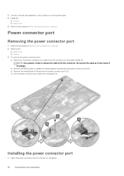
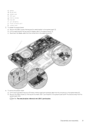
... on the system board. 4. b) Remove the M2x3 screw to the connector on the laptop. 28 Disassembly and reassembly Install the: a) battery b) base cover 5. To remove the power connector port: a) Disconnect the power connector port cable from the connector. Connect the heat sink... assembly to release the metal bracket that secures the power connector port [3]. Remove the: a) base cover b) battery 3. 3. c) Remove the metal bracket that secures the power connector port [2]. d) Lift the power connector port away from the laptop [4]. ...
... on the system board. 4. b) Remove the M2x3 screw to the connector on the laptop. 28 Disassembly and reassembly Install the: a) battery b) base cover 5. To remove the power connector port: a) Disconnect the power connector port cable from the connector. Connect the heat sink... assembly to release the metal bracket that secures the power connector port [3]. Remove the: a) base cover b) battery 3. 3. c) Remove the metal bracket that secures the power connector port [2]. d) Lift the power connector port away from the laptop [4]. ...

Service Manual
Page 29
Install the: a) battery b) base cover 6. Follow the procedure in Before working inside your computer. Chassis frame Removing the chassis frame 1. Follow the procedure in After working inside your ... board. 5. Place the metal bracket on the system board. 4. To remove the chassis frame: Disassembly and reassembly 29 Remove the: a) SIM card module b) base cover c) battery d) WLAN card e) WWAN card f) SSD card 3.
Install the: a) battery b) base cover 6. Follow the procedure in Before working inside your computer. Chassis frame Removing the chassis frame 1. Follow the procedure in After working inside your ... board. 5. Place the metal bracket on the system board. 4. To remove the chassis frame: Disassembly and reassembly 29 Remove the: a) SIM card module b) base cover c) battery d) WLAN card e) WWAN card f) SSD card 3.

Service Manual
Page 30
... the laptop[1]. b) Lift the chassis frame away from the laptop [2]. Install the: a) SSD card b) WWAN card c) WLAN card d) battery e) base cover f) SIM card module 5. Installing the chassis frame 1. NOTE: Ensure the coin cell battery cable is properly routed in After working inside your computer. 2. System board Removing the system board 1. Place the...
... the laptop[1]. b) Lift the chassis frame away from the laptop [2]. Install the: a) SSD card b) WWAN card c) WLAN card d) battery e) base cover f) SIM card module 5. Installing the chassis frame 1. NOTE: Ensure the coin cell battery cable is properly routed in After working inside your computer. 2. System board Removing the system board 1. Place the...
Service Manual
Page 31
... e) WWAN card f) SSD card g) memory module h) heat sink i) coin cell battery j) Power connector port k) chassis frame 3. To remove the system board: a) Lift the latch and disconnect the LED board, mother board and touchpad cable from the ...
... e) WWAN card f) SSD card g) memory module h) heat sink i) coin cell battery j) Power connector port k) chassis frame 3. To remove the system board: a) Lift the latch and disconnect the LED board, mother board and touchpad cable from the ...

Service Manual
Page 33
...-C bracket and tighten the M2x5 screws on the system board. 6. Install the: a) chassis frame b) Power connector port c) coin cell battery d) heat sink e) memory module f) SSD card g) WWAN card h) WLAN card i) battery j) base cover k) SIM card module 8. b) Peel off the SmartCard reader cable from the connector on the laptop. 2. Touchpad Removing ...working inside your computer. 2. Align the system board with the screw holders on the system board [1]. Installing the system board 1. Remove the: a) base cover b) battery c) WLAN card d) WWAN card e) SSD card f) chassis frame 3.
...-C bracket and tighten the M2x5 screws on the system board. 6. Install the: a) chassis frame b) Power connector port c) coin cell battery d) heat sink e) memory module f) SSD card g) WWAN card h) WLAN card i) battery j) base cover k) SIM card module 8. b) Peel off the SmartCard reader cable from the connector on the laptop. 2. Touchpad Removing ...working inside your computer. 2. Align the system board with the screw holders on the system board [1]. Installing the system board 1. Remove the: a) base cover b) battery c) WLAN card d) WWAN card e) SSD card f) chassis frame 3.


