
Getting Started Guide
Page 5
.... • Support for up your system. Availability Features • Up to two active/active RAID controller modules (duplex configuration) for a total of 45 physical disks. • Controller capable of a power outage • Redundant hot-plug power supply and cooling modules that are combined for... describes the major hardware and software features of servers. (For additional support information, refer to the Dell PowerVault MD Systems Support Matrix at support.dell.com). • Support for easy serviceability Getting Started With Your System 3 For more information, refer to the...
.... • Support for up your system. Availability Features • Up to two active/active RAID controller modules (duplex configuration) for a total of 45 physical disks. • Controller capable of a power outage • Redundant hot-plug power supply and cooling modules that are combined for... describes the major hardware and software features of servers. (For additional support information, refer to the Dell PowerVault MD Systems Support Matrix at support.dell.com). • Support for easy serviceability Getting Started With Your System 3 For more information, refer to the...

Getting Started Guide
Page 7
...provide documentation and tools for installing, configuring, and managing your system. • The Dell PowerVault MD Systems Support Matrix at support.dell.com provides compatibility information, including servers, operating systems, controllers, software, and hardware configurations. • Updates are sometimes included with your system....procedure in case you need them later. This section describes the steps to the Installation Guide provided on support.dell.com and read and follow the safety instructions and important regulatory information in all shipping materials in this guide...
...provide documentation and tools for installing, configuring, and managing your system. • The Dell PowerVault MD Systems Support Matrix at support.dell.com provides compatibility information, including servers, operating systems, controllers, software, and hardware configurations. • Updates are sometimes included with your system....procedure in case you need them later. This section describes the steps to the Installation Guide provided on support.dell.com and read and follow the safety instructions and important regulatory information in all shipping materials in this guide...

Getting Started Guide
Page 10
Cable the RAID controller modules according to the instructions provided in the Hardware Owner's Manual. 8 Getting Started With Your System Plug the other end of the power cables into a grounded electrical outlet or a separate power source such as an uninterruptible power supply (UPS) or a power distribution unit (PDU).
Cable the RAID controller modules according to the instructions provided in the Hardware Owner's Manual. 8 Getting Started With Your System Plug the other end of the power cables into a grounded electrical outlet or a separate power source such as an uninterruptible power supply (UPS) or a power distribution unit (PDU).

Getting Started Guide
Page 12
... hot-pluggable active/active controllers (or one controller in simplex mode) • 512 MB of cache per controller • Simplex or duplex configurations • One temperature sensor per controller RAID Controller Back-Panel Connectors iSCSI ports (per RAID controller) SAS expansion port (per RAID controller) Debug connector (per RAID controller) Management port (per RAID controller) • One 100/1000...
... hot-pluggable active/active controllers (or one controller in simplex mode) • 512 MB of cache per controller • Simplex or duplex configurations • One temperature sensor per controller RAID Controller Back-Panel Connectors iSCSI ports (per RAID controller) SAS expansion port (per RAID controller) Debug connector (per RAID controller) Management port (per RAID controller) • One 100/1000...
Getting Started Guide
Page 13
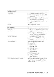
...15 SAS physical-disk connectors • Two power supply/cooling fan module connectors • Two sets of RAID controller connectors (six connectors each controller) • One control panel connector for front LEDs Two temperature sensors • One two-color LED indicator for system status •...8226; One two-color LED status indicator per disk The following single-color LEDs: • Battery fault • Cache active • Controller fault • Controller power • Ethernet link • Ethernet activity • SAS Out fault/active • iSCSI In fault (2) • iSCSI In ...
...15 SAS physical-disk connectors • Two power supply/cooling fan module connectors • Two sets of RAID controller connectors (six connectors each controller) • One control panel connector for front LEDs Two temperature sensors • One two-color LED indicator for system status •...8226; One two-color LED status indicator per disk The following single-color LEDs: • Battery fault • Cache active • Controller fault • Controller power • Ethernet link • Ethernet activity • SAS Out fault/active • iSCSI In fault (2) • iSCSI In ...
Hardware Owner's Manual
Page 3
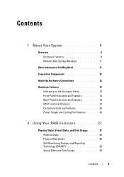
... Enclosure Connections 12 Hardware Features 13 Indicators on the Enclosure Bezel 13 Front-Panel Indicators and Features 14 Back-Panel Indicators and Features 18 RAID Controller Modules 18 Cache Functions and Features 24 Power Supply and Cooling Fan Features . . . . . 24 2 Using Your RAID Enclosure 27 Physical Disks, Virtual Disks, and Disk...
... Enclosure Connections 12 Hardware Features 13 Indicators on the Enclosure Bezel 13 Front-Panel Indicators and Features 14 Back-Panel Indicators and Features 18 RAID Controller Modules 18 Cache Functions and Features 24 Power Supply and Cooling Fan Features . . . . . 24 2 Using Your RAID Enclosure 27 Physical Disks, Virtual Disks, and Disk...
Hardware Owner's Manual
Page 5
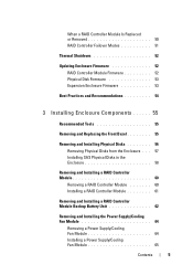
... Modes 51 Thermal Shutdown 52 Updating Enclosure Firmware 52 RAID Controller Module Firmware 52 Physical Disk Firmware 53 Expansion Enclosure Firmware 53 Best Practices and Recommendations 54 3 Installing Enclosure Components 55 ... Enclosure . . . 57 Installing SAS Physical Disks in the Enclosure 58 Removing and Installing a RAID Controller Module 60 Removing a RAID Controller Module 60 Installing a RAID Controller Module 61 Removing and Installing a RAID Controller Module Backup Battery Unit 62 Removing and Installing the Power Supply/Cooling Fan Module 64 Removing a Power ...
... Modes 51 Thermal Shutdown 52 Updating Enclosure Firmware 52 RAID Controller Module Firmware 52 Physical Disk Firmware 53 Expansion Enclosure Firmware 53 Best Practices and Recommendations 54 3 Installing Enclosure Components 55 ... Enclosure . . . 57 Installing SAS Physical Disks in the Enclosure 58 Removing and Installing a RAID Controller Module 60 Removing a RAID Controller Module 60 Installing a RAID Controller Module 61 Removing and Installing a RAID Controller Module Backup Battery Unit 62 Removing and Installing the Power Supply/Cooling Fan Module 64 Removing a Power ...

Hardware Owner's Manual
Page 6
Removing and Installing the Control Panel 66 Removing the Control Panel 66 Installing the Control Panel 67 Removing and Installing the Midplane 68 4 Troubleshooting Your Enclosure 71 Safety First-For You and Your Enclosure 71 ...Troubleshooting Power Supplies 73 Troubleshooting Enclosure Cooling Problems . . . . . 75 Troubleshooting a Fan 75 Troubleshooting SAS Physical Disks 76 Troubleshooting Enclosure Connections 77 Hard Controller Failures and Lockdown Conditions 78 Invalid Enclosure 78 ECC Errors 78 PCI Errors 79 Critical Conditions 79 Noncritical Conditions 79 6 Contents
Removing and Installing the Control Panel 66 Removing the Control Panel 66 Installing the Control Panel 67 Removing and Installing the Midplane 68 4 Troubleshooting Your Enclosure 71 Safety First-For You and Your Enclosure 71 ...Troubleshooting Power Supplies 73 Troubleshooting Enclosure Cooling Problems . . . . . 75 Troubleshooting a Fan 75 Troubleshooting SAS Physical Disks 76 Troubleshooting Enclosure Connections 77 Hard Controller Failures and Lockdown Conditions 78 Invalid Enclosure 78 ECC Errors 78 PCI Errors 79 Critical Conditions 79 Noncritical Conditions 79 6 Contents
Hardware Owner's Manual
Page 9
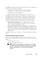
... to a maximum of 45 disks in two supported configurations: - Dual-controller configurations for both single RAID controller configuration and dual RAID controller configuration. Overview The RAID enclosure is established through an iSCSI initiator. For...controller configurations - The MD3000i storage array provides dual active/active RAID controller modules, redundant power supplies, and redundant fans. Enclosure Features Features include: • Support for high availability, offering redundant access to data storage. About Your System The Dell™ PowerVault™ MD3000i...
... to a maximum of 45 disks in two supported configurations: - Dual-controller configurations for both single RAID controller configuration and dual RAID controller configuration. Overview The RAID enclosure is established through an iSCSI initiator. For...controller configurations - The MD3000i storage array provides dual active/active RAID controller modules, redundant power supplies, and redundant fans. Enclosure Features Features include: • Support for high availability, offering redundant access to data storage. About Your System The Dell™ PowerVault™ MD3000i...
Hardware Owner's Manual
Page 10
Physical disk NOTE: Dell recommends stopping all I /O activity from a failed, offline, or removed RAID controller module to the array when downloading physical disk firmware. - Expansion enclosure management modules (EMMs) • Task-based configuration software ...to 255 virtual disk copies per array • Optional virtual disk copy (premium feature), up to two PowerVault MD1000 expansion enclosures through SAS Out port connectors on the RAID controller modules • Online firmware updates (without taking the enclosure offline) for redundant configurations to automatically reroute I...
Physical disk NOTE: Dell recommends stopping all I /O activity from a failed, offline, or removed RAID controller module to the array when downloading physical disk firmware. - Expansion enclosure management modules (EMMs) • Task-based configuration software ...to 255 virtual disk copies per array • Optional virtual disk copy (premium feature), up to two PowerVault MD1000 expansion enclosures through SAS Out port connectors on the RAID controller modules • Online firmware updates (without taking the enclosure offline) for redundant configurations to automatically reroute I...

Hardware Owner's Manual
Page 12
... connecting your RAID enclosure, including: - Setting Up Your PowerVault MD3000i - • Updates are sometimes included to describe changes to the host server. MD3000i Resource CD - Rack Installation Guide or Rack Installation Instructions - The RAID controller modules are labeled 0 and 1. 12 About Your System ...check for updates on support.dell.com and read the updates first because they often supersede information in other documents. • Release notes or readme files are included to provide last-minute updates to a host server via two RAID controller modules. Power cords (2) ...
... connecting your RAID enclosure, including: - Setting Up Your PowerVault MD3000i - • Updates are sometimes included to describe changes to the host server. MD3000i Resource CD - Rack Installation Guide or Rack Installation Instructions - The RAID controller modules are labeled 0 and 1. 12 About Your System ...check for updates on support.dell.com and read the updates first because they often supersede information in other documents. • Release notes or readme files are included to provide last-minute updates to a host server via two RAID controller modules. Power cords (2) ...

Hardware Owner's Manual
Page 13
... 2 3 About Your System 13 LEDs on the bezel. Figure 1-1 illustrates the indicators and components on page 55. Refer to the PowerVault MD3000i Installation Guide for details and illustrated examples of the enclosure to limit access. Figure 1-1. Hardware Features The remainder of this section describes the.... For information on installing and removing the bezel, see "Removing and Replacing the Front Bezel" on the bezel. Each MD3000i RAID controller module also contains a SAS Out port connector. This port allows you the option to connect the RAID enclosure to configure your ...
... 2 3 About Your System 13 LEDs on the bezel. Figure 1-1 illustrates the indicators and components on page 55. Refer to the PowerVault MD3000i Installation Guide for details and illustrated examples of the enclosure to limit access. Figure 1-1. Hardware Features The remainder of this section describes the.... For information on installing and removing the bezel, see "Removing and Replacing the Front Bezel" on the bezel. Each MD3000i RAID controller module also contains a SAS Out port connector. This port allows you the option to connect the RAID enclosure to configure your ...

Hardware Owner's Manual
Page 18
... page 24. A fully populated enclosure with the other controller's cache for high availability and protected by a battery for up to 72 hours. 18 About Your System Figure 1-4. However, a single RAID controller module is shown. For more information, see "Power ...one power supply/cooling fan module. Each RAID controller module contains 512 MB of the enclosure. Back-Panel Features 1 2 3 1 RAID controller module 0 2 RAID controller module 1 3 power supply/cooling fan modules (2) RAID Controller Modules The RAID controller modules provide high-performance, advanced virtual disk ...
... page 24. A fully populated enclosure with the other controller's cache for high availability and protected by a battery for up to 72 hours. 18 About Your System Figure 1-4. However, a single RAID controller module is shown. For more information, see "Power ...one power supply/cooling fan module. Each RAID controller module contains 512 MB of the enclosure. Back-Panel Features 1 2 3 1 RAID controller module 0 2 RAID controller module 1 3 power supply/cooling fan modules (2) RAID Controller Modules The RAID controller modules provide high-performance, advanced virtual disk ...
Hardware Owner's Manual
Page 19
...Ethernet Switch. If a DHCP server is not available (time-out is 10 seconds) then the RAID controller modules uses the static IP addresses of 192.168.128.101 for controller 0 and 192.168.128.102 for each client through the use of the enclosure. About Your System... 19 Various configurations can be utilized, in both single controller and dual controller mode, to connect the storage enclosure to hosts depending on cabling, see the PowerVault MD3000i Installation Guide...
...Ethernet Switch. If a DHCP server is not available (time-out is 10 seconds) then the RAID controller modules uses the static IP addresses of 192.168.128.101 for controller 0 and 192.168.128.102 for each client through the use of the enclosure. About Your System... 19 Various configurations can be utilized, in both single controller and dual controller mode, to connect the storage enclosure to hosts depending on cabling, see the PowerVault MD3000i Installation Guide...
Hardware Owner's Manual
Page 20
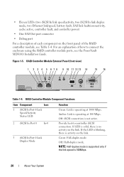
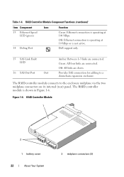
...activity on the link. RAID Controller Module External Panel (front view) 1 2 3 4 5 6 7 8 9 10 11 12 13 14 15 16 Table 1-4. Off: Half-duplex mode. Green: Full-duplex mode. For an explanation of the RAID controller module, see the PowerVault MD3000i Installation Guide. If the LED... is blinking, there is no activity on the link. RAID Controller Module Component Functions Item Component Icon 1 iSCSI In Port 0 Link Speed/...
...activity on the link. RAID Controller Module External Panel (front view) 1 2 3 4 5 6 7 8 9 10 11 12 13 14 15 16 Table 1-4. Off: Half-duplex mode. Green: Full-duplex mode. For an explanation of the RAID controller module, see the PowerVault MD3000i Installation Guide. If the LED... is blinking, there is no activity on the link. RAID Controller Module Component Functions Item Component Icon 1 iSCSI In Port 0 Link Speed/...

Hardware Owner's Manual
Page 21
...: Ethernet connection is not active. About Your System 21 Provide host-to-controller iSCSI connection. Off: Controller is operating normally. 10 Controller Power LED (green) Green: Controller power is operating at 100 Mbps. RAID Controller Module Component Functions (continued) Item Component Icon 4 iSCSI In Port 1...LED (green) 7 iSCSI In Port 1 In-1 8 iSCSI In Port 1 Link Duplex Mode 9 Controller Fault LED (amber) Function Green: Link is on the link. Off: On-board controller memory is active. If the LED is blinking, there is operating at 1000 Mbps. Off: Half-...
...: Ethernet connection is not active. About Your System 21 Provide host-to-controller iSCSI connection. Off: Controller is operating normally. 10 Controller Power LED (green) Green: Controller power is operating at 100 Mbps. RAID Controller Module Component Functions (continued) Item Component Icon 4 iSCSI In Port 1...LED (green) 7 iSCSI In Port 1 In-1 8 iSCSI In Port 1 Link Duplex Mode 9 Controller Fault LED (amber) Function Green: Link is on the link. Off: On-board controller memory is active. If the LED is blinking, there is operating at 1000 Mbps. Off: Half-...
Hardware Owner's Manual
Page 22
...About Your System 2 midplane connectors (2) Table 1-4. Dell support only. 15 SAS Link Fault LED 16 SAS Out Port Out Amber: Between 1-3 links are connected. The RAID controller module is not active. Off: All links are down. The RAID controller module connects to a downchain expansion enclosure. Figure... SAS connection for cabling to the enclosure midplane via the two midplane connectors on its internal (rear) panel. RAID Controller Module Component Functions (continued) Item Component Icon 13 Ethernet Speed LED (green) 14 Debug Port Function Green: Ethernet connection...
...About Your System 2 midplane connectors (2) Table 1-4. Dell support only. 15 SAS Link Fault LED 16 SAS Out Port Out Amber: Between 1-3 links are connected. The RAID controller module is not active. Off: All links are down. The RAID controller module connects to a downchain expansion enclosure. Figure... SAS connection for cabling to the enclosure midplane via the two midplane connectors on its internal (rear) panel. RAID Controller Module Component Functions (continued) Item Component Icon 13 Ethernet Speed LED (green) 14 Debug Port Function Green: Ethernet connection...

Hardware Owner's Manual
Page 23
... loss for all data in the cache is saved. For a description of the battery fault LED, see "Removing and Installing a RAID Controller Module Backup Battery Unit" on the state of up to determine the temperature at startup and will illuminate the battery fault LED if the ...threshold. These thresholds are used to 72 hours, all virtual disks. The battery begins recharging automatically if the test determines that powers the controller's cache memory and preserves the cache contents in the event of the enclosure power supplies occurs within specified ranges, or if the battery is...
... loss for all data in the cache is saved. For a description of the battery fault LED, see "Removing and Installing a RAID Controller Module Backup Battery Unit" on the state of up to determine the temperature at startup and will illuminate the battery fault LED if the ...threshold. These thresholds are used to 72 hours, all virtual disks. The battery begins recharging automatically if the test determines that powers the controller's cache memory and preserves the cache contents in the event of the enclosure power supplies occurs within specified ranges, or if the battery is...

Hardware Owner's Manual
Page 24
...Cache Write-through cache is returned to the host. This action ensures that hostwrite data is safely mirrored to the partner controller before completion status is considered more appropriate time in a completion signal being sent to the host operating system as soon ... strategy whereby data is written to the physical disk before successful completion status is less likely to the partner controller. If a controller fails, the surviving controller safely retains all mirrored data. Cache Functions and Features Cache Mirroring The cache mirroring function copies accepted host-write...
...Cache Write-through cache is returned to the host. This action ensures that hostwrite data is safely mirrored to the partner controller before completion status is considered more appropriate time in a completion signal being sent to the host operating system as soon ... strategy whereby data is written to the physical disk before successful completion status is less likely to the partner controller. If a controller fails, the surviving controller safely retains all mirrored data. Cache Functions and Features Cache Mirroring The cache mirroring function copies accepted host-write...
Hardware Owner's Manual
Page 28
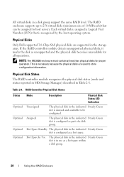
... Steady Green slot is unused and available to store configuration information. Physical Disks Only Dell-supported 3.0-Gbps SAS physical disks are used to be assigned to host servers. NOTE: The MD3000i enclosure must contain at least two physical disks for all operations. Table 2-1. Hot ... indicated Steady Green slot is configured as unsupported and the physical disk becomes unavailable for proper operation. Physical Disk States The RAID controller module recognizes the physical disk states (mode and status reported in MD Storage Manager) described in the storage array. Assigned The ...
... Steady Green slot is unused and available to store configuration information. Physical Disks Only Dell-supported 3.0-Gbps SAS physical disks are used to be assigned to host servers. NOTE: The MD3000i enclosure must contain at least two physical disks for all operations. Table 2-1. Hot ... indicated Steady Green slot is configured as unsupported and the physical disk becomes unavailable for proper operation. Physical Disk States The RAID controller module recognizes the physical disk states (mode and status reported in MD Storage Manager) described in the storage array. Assigned The ...


