
Glossary
Page 8
... circuit board, the system board usually contains most of your system in a series, you change them again. Because the System Setup program is the same on a network hub or switch used . Super video graphics array. USB devices can be connected and disconnected...(unbuffered) DDR3 memory module. A port on each disk. See memory key. 8 Used to I/O devices. See also guarding, mirroring, and RAID. USB - System Setup program - SNMP - Some devices (such as mice and keyboards. Transmission Control Protocol/Internet Protocol. TCP/IP offload engine.
... circuit board, the system board usually contains most of your system in a series, you change them again. Because the System Setup program is the same on a network hub or switch used . Super video graphics array. USB devices can be connected and disconnected...(unbuffered) DDR3 memory module. A port on each disk. See memory key. 8 Used to I/O devices. See also guarding, mirroring, and RAID. USB - System Setup program - SNMP - Some devices (such as mice and keyboards. Transmission Control Protocol/Internet Protocol. TCP/IP offload engine.
Dell PowerEdge Deployment Guide
Page 4
...www.support.dell.com. ...10th Generation PowerEdge servers. ...dell.com for the network adapters to setup a deployment infrastructure, but rather the modifications needed in the 11th Generation PowerEdge servers. The 11th Generation PowerEdge servers include 5709-based LOMs (LAN-on these servers. This document will not cover how to support iSCSI and TOE. Failing to Dell PowerEdge...Page 2 PowerEdge Deployment Guide ... Generation PowerEdge servers....Microsoft Windows on Dell Servers with Broadcom...Dell logo being displayed during installation. Press the key within 10 seconds of text-mode setup...
...www.support.dell.com. ...10th Generation PowerEdge servers. ...dell.com for the network adapters to setup a deployment infrastructure, but rather the modifications needed in the 11th Generation PowerEdge servers. The 11th Generation PowerEdge servers include 5709-based LOMs (LAN-on these servers. This document will not cover how to support iSCSI and TOE. Failing to Dell PowerEdge...Page 2 PowerEdge Deployment Guide ... Generation PowerEdge servers....Microsoft Windows on Dell Servers with Broadcom...Dell logo being displayed during installation. Press the key within 10 seconds of text-mode setup...
Dell PowerEdge Deployment Guide
Page 5
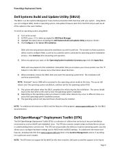
SBUU will reboot when the SBUU completes the initial setup for the installation. Click Continue after answering each question. 5) Select any options you chose to these questions will be installed. The server will reboot, ...for BIOS Boot Manager. 3) Highlight the optical drive containing the Dell Systems Build and Update Utility and press . 4) Click Configure in the user interface. PowerEdge Deployment Guide Dell Systems Build and Update Utility (SBUU) The SBUU is a collection of utilities that can configure RAID, install an operating system, and update firmware. The answers ...
SBUU will reboot when the SBUU completes the initial setup for the installation. Click Continue after answering each question. 5) Select any options you chose to these questions will be installed. The server will reboot, ...for BIOS Boot Manager. 3) Highlight the optical drive containing the Dell Systems Build and Update Utility and press . 4) Click Configure in the user interface. PowerEdge Deployment Guide Dell Systems Build and Update Utility (SBUU) The SBUU is a collection of utilities that can configure RAID, install an operating system, and update firmware. The answers ...

Hardware Owner's Manual
Page 3
Contents 1 About Your System 11 Accessing System Features During Startup 11 Front-Panel Features and Indicators 12 LCD Panel Features 14 Home Screen 15 Setup Menu 16 View Menu 16 Hard-Drive Indicator Patterns for RAID 17 Back-Panel Features and Indicators 19 Power Indicator Codes 21 NIC Indicator Codes 22 LCD Status Messages 23 Viewing Status Messages 23 Removing LCD Status Messages 23 System Messages 37 Warning Messages 54 Diagnostics Messages 54 Alert Messages 54 Other Information You May Need 55 Contents 3
Contents 1 About Your System 11 Accessing System Features During Startup 11 Front-Panel Features and Indicators 12 LCD Panel Features 14 Home Screen 15 Setup Menu 16 View Menu 16 Hard-Drive Indicator Patterns for RAID 17 Back-Panel Features and Indicators 19 Power Indicator Codes 21 NIC Indicator Codes 22 LCD Status Messages 23 Viewing Status Messages 23 Removing LCD Status Messages 23 System Messages 37 Warning Messages 54 Diagnostics Messages 54 Alert Messages 54 Other Information You May Need 55 Contents 3

Hardware Owner's Manual
Page 17
Hard-Drive Indicator Patterns for RAID Figure 1-3. The display format can be configured in Celsius or Fahrenheit. Hard Drive Indicators 1 2 1 drive-activity indicator (green) 2 drive-status indicator (green and amber) About Your System 17 Option Temperature Description Displays the temperature of the system in the "Set home" submenu of the Setup menu (see "Setup Menu").
Hard-Drive Indicator Patterns for RAID Figure 1-3. The display format can be configured in Celsius or Fahrenheit. Hard Drive Indicators 1 2 1 drive-activity indicator (green) 2 drive-status indicator (green and amber) About Your System 17 Option Temperature Description Displays the temperature of the system in the "Set home" submenu of the Setup menu (see "Setup Menu").

Hardware Owner's Manual
Page 24
...Help." Memory has exceeded allowable temperature and has been disabled to prevent damage to the system for 10 seconds and restart the system. Reseat the RAID battery connector. Power cycle AC. system for critical failure events. Problems." If the problem persists, see "Getting Help." E1114 Ambient Temp exceeds allowed...power to the components. To resolve the problem and remove the LCD message, refer to the corrective actions in the Simple format. See "Setup Menu"to select the format in which the messages are displayed in the following LCD status messages are displayed.
...Help." Memory has exceeded allowable temperature and has been disabled to prevent damage to the system for 10 seconds and restart the system. Reseat the RAID battery connector. Power cycle AC. system for critical failure events. Problems." If the problem persists, see "Getting Help." E1114 Ambient Temp exceeds allowed...power to the components. To resolve the problem and remove the LCD message, refer to the corrective actions in the Simple format. See "Setup Menu"to select the format in which the messages are displayed in the following LCD status messages are displayed.

Hardware Owner's Manual
Page 64
... DMA Engine (Disabled default) When supported, this option enables or disables the I/O Acceleration Technology feature. 64 Using the System Setup Program and UEFI Boot Manager Integrated Devices Screen Option Description Integrated SAS/RAID Controller (Enabled default) Enables or disables the integrated storage controller. User Accessible USB Ports Enables or disables the user...
... DMA Engine (Disabled default) When supported, this option enables or disables the I/O Acceleration Technology feature. 64 Using the System Setup Program and UEFI Boot Manager Integrated Devices Screen Option Description Integrated SAS/RAID Controller (Enabled default) Enables or disables the integrated storage controller. User Accessible USB Ports Enables or disables the user...

Hardware Owner's Manual
Page 153
See "Removing a Hot-Swap Hard Drive." See "Using the System Setup Program and UEFI Boot Manager." NOTE: When troubleshooting a SAS or SAS RAID controller, also see "Troubleshooting a SAS Controller." a Restart the system and enter the host adapter configuration utility ...drivers for your hard drives are configured correctly. Troubleshooting a SAS Controller . See "Running the System Diagnostics." 2 Enter the System Setup program and ensure that the hard drive(s) have been configured correctly for information about the configuration utility. b Ensure that the SAS or...
See "Removing a Hot-Swap Hard Drive." See "Using the System Setup Program and UEFI Boot Manager." NOTE: When troubleshooting a SAS or SAS RAID controller, also see "Troubleshooting a SAS Controller." a Restart the system and enter the host adapter configuration utility ...drivers for your hard drives are configured correctly. Troubleshooting a SAS Controller . See "Running the System Diagnostics." 2 Enter the System Setup program and ensure that the hard drive(s) have been configured correctly for information about the configuration utility. b Ensure that the SAS or...

Hardware Owner's Manual
Page 175
...- Serial Advanced Technology Attachment. Secure digital flash memory card. sec - Self-Monitoring Analysis and Reporting Technology. See also guarding, mirroring, and RAID. SD card - SDRAM - A standard interface that tells a system what hardware is stored in NVRAM, any settings remain in an array... usually contains most often used by a "stripe" is most of disks in effect until you to identify it when you call Dell for operation. System Setup program - Solid State Drives. SAS - Synchronous dynamic random-access memory. A legacy I /O bus interface. SCSI - Used to...
...- Serial Advanced Technology Attachment. Secure digital flash memory card. sec - Self-Monitoring Analysis and Reporting Technology. See also guarding, mirroring, and RAID. SD card - SDRAM - A standard interface that tells a system what hardware is stored in NVRAM, any settings remain in an array... usually contains most often used by a "stripe" is most of disks in effect until you to identify it when you call Dell for operation. System Setup program - Solid State Drives. SAS - Synchronous dynamic random-access memory. A legacy I /O bus interface. SCSI - Used to...

Hardware Owner's Manual
Page 182
P password setup, 74 system, 72 passwords disabling, 163 PERC 6/I battery cable, 114 removing bezel, 78 control panel board, ... drives, 83 information tag, 79 internal USB cable, 99 memory modules, 122 power supply, 87 power supply blank, 89 processor, 122 RAID battery, 114 SAS backplane board, 132 SAS controller, 111 SD card, 98 system board, 135 replacing cooling fan, 106 information tag,..., 87 replacing, 88 troubleshooting, 146 power supply blank, 89 processor installing, 125 removing, 122 troubleshooting, 157 R RAID battery installing, 114 removing, 114 remote access controller See iDRAC.
P password setup, 74 system, 72 passwords disabling, 163 PERC 6/I battery cable, 114 removing bezel, 78 control panel board, ... drives, 83 information tag, 79 internal USB cable, 99 memory modules, 122 power supply, 87 power supply blank, 89 processor, 122 RAID battery, 114 SAS backplane board, 132 SAS controller, 111 SD card, 98 system board, 135 replacing cooling fan, 106 information tag,..., 87 replacing, 88 troubleshooting, 146 power supply blank, 89 processor installing, 125 removing, 122 troubleshooting, 157 R RAID battery installing, 114 removing, 114 remote access controller See iDRAC.

Hardware Owner's Manual
Page 183
... features, 11 support contacting Dell, 167 system closing, 81 opening, 80 system board connectors, 164 installing, 138 jumpers, 163 removing, 135 system cooling troubleshooting, 147 system features accessing, 11 system messages, 37 system password, 72 system setup program boot settings, 63 embedded... 145 expansion cards, 155 external connections, 141 Index 183 installing, 112 removing, 111 SAS controller daughter card troubleshooting, 153 SAS RAID controller daughter card troubleshooting, 153 SD card installing, 97 removing, 98 troubleshooting, 150-151 securing your system, 68, 73 service...
... features, 11 support contacting Dell, 167 system closing, 81 opening, 80 system board connectors, 164 installing, 138 jumpers, 163 removing, 135 system cooling troubleshooting, 147 system features accessing, 11 system messages, 37 system password, 72 system setup program boot settings, 63 embedded... 145 expansion cards, 155 external connections, 141 Index 183 installing, 112 removing, 111 SAS controller daughter card troubleshooting, 153 SAS RAID controller daughter card troubleshooting, 153 SD card installing, 97 removing, 98 troubleshooting, 150-151 securing your system, 68, 73 service...


