
Glossary
Page 8
... cable. termination - TCP/IP offload engine. An unregistered (unbuffered) DDR3 memory module. A battery-powered unit that allows you change them again. A USB connector provides a single connection point ...only uses a portion of an electrical failure. system memory - System Setup program - Transmission Control Protocol/Internet Protocol. SNMP - TOE - USB devices can be terminated to remotely monitor and...previous standards. Universal Serial Bus. UPS - See also guarding, mirroring, and RAID. Super video graphics array. A port on each disk. USB memory key -...
... cable. termination - TCP/IP offload engine. An unregistered (unbuffered) DDR3 memory module. A battery-powered unit that allows you change them again. A USB connector provides a single connection point ...only uses a portion of an electrical failure. system memory - System Setup program - Transmission Control Protocol/Internet Protocol. SNMP - TOE - USB devices can be terminated to remotely monitor and...previous standards. Universal Serial Bus. UPS - See also guarding, mirroring, and RAID. Super video graphics array. A port on each disk. USB memory key -...
Hardware Owner's Manual
Page 7
... Removing an Optical Drive 109 Installing an Optical Drive 110 Integrated Storage Controller Card 111 Removing the Integrated Storage Controller Card 111 Installing the Integrated Storage Controller Card 112 RAID Battery 114 Removing a RAID Battery 114 Installing a RAID Battery 114 Removing the PERC 6/I Battery Cable 114 Installing the PERC 6/I Battery Cable 115 System Memory 116 General Memory Module Installation Guidelines 116...
... Removing an Optical Drive 109 Installing an Optical Drive 110 Integrated Storage Controller Card 111 Removing the Integrated Storage Controller Card 111 Installing the Integrated Storage Controller Card 112 RAID Battery 114 Removing a RAID Battery 114 Installing a RAID Battery 114 Removing the PERC 6/I Battery Cable 114 Installing the PERC 6/I Battery Cable 115 System Memory 116 General Memory Module Installation Guidelines 116...

Hardware Owner's Manual
Page 24
... to thermal issues. LCD Status Messages Code Text E1000 Failsafe voltage error. E1116 Memory disabled, temp above range. E1210 Motherboard battery failure. E1211 RAID Controller battery failure. system for critical failure events. Reseat the RAID battery connector. See "Setup Menu"to select the format in which the messages are displayed in the following LCD status messages...
... to thermal issues. LCD Status Messages Code Text E1000 Failsafe voltage error. E1116 Memory disabled, temp above range. E1210 Motherboard battery failure. E1211 RAID Controller battery failure. system for critical failure events. Reseat the RAID battery connector. See "Setup Menu"to select the format in which the messages are displayed in the following LCD status messages...

Hardware Owner's Manual
Page 36
... Text Cause Corrective Actions W1228 RAID Controller battery capacity < 24hr. Turn off power to the system, reduce the hardware configuration or install higher-wattage power supplies, and then restart the system. Warns predictively that the Allow RAID battery to RAID battery has less than charge to greater...supply can provide, but it can provide. If problem persists, replace the RAID battery. The system configuration requires more power than 24 24 hours of charge left. See "Installing a RAID Battery." NOTE: For the full name of sustained charge. hours of an ...
... Text Cause Corrective Actions W1228 RAID Controller battery capacity < 24hr. Turn off power to the system, reduce the hardware configuration or install higher-wattage power supplies, and then restart the system. Warns predictively that the Allow RAID battery to RAID battery has less than charge to greater...supply can provide, but it can provide. If problem persists, replace the RAID battery. The system configuration requires more power than 24 24 hours of charge left. See "Installing a RAID Battery." NOTE: For the full name of sustained charge. hours of an ...

Hardware Owner's Manual
Page 78
... supply bays (2) 3 iDRAC6 Enterprise card 5 memory modules (12) 7 SAS backplane 9 optical drive 11 Internal SD Module 8 2 expansion-card riser (2) 4 integrated storage controller card 6 heat sink/processor (2) 8 hard drives (6) 10 RAID battery (PERC only) 12 fans (5 or 6) Removing and Replacing the Optional Front Bezel 1 Unlock the keylock at the left end of the bezel...
... supply bays (2) 3 iDRAC6 Enterprise card 5 memory modules (12) 7 SAS backplane 9 optical drive 11 Internal SD Module 8 2 expansion-card riser (2) 4 integrated storage controller card 6 heat sink/processor (2) 8 hard drives (6) 10 RAID battery (PERC only) 12 fans (5 or 6) Removing and Replacing the Optional Front Bezel 1 Unlock the keylock at the left end of the bezel...
Hardware Owner's Manual
Page 111
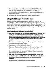
... System Components 111 Damage due to servicing that provides the integrated storage subsystem for an integrated SAS or PERC controller card that is not authorized by Dell is not covered by a certified service technician. Read and follow the safety instructions that data is lit. ... as supported by the online or telephone service and support team. The controller supports SAS and SATA hard drives and also enables you are removing a battery-cached PERC controller, disconnect the RAID battery cable from the controller card. See Figure 3-17. The LED indicates that came with your ...
... System Components 111 Damage due to servicing that provides the integrated storage subsystem for an integrated SAS or PERC controller card that is not authorized by Dell is not covered by a certified service technician. Read and follow the safety instructions that data is lit. ... as supported by the online or telephone service and support team. The controller supports SAS and SATA hard drives and also enables you are removing a battery-cached PERC controller, disconnect the RAID battery cable from the controller card. See Figure 3-17. The LED indicates that came with your ...

Hardware Owner's Manual
Page 113
... Figure 3-14, "Removing a Cooling Fan," and "Replacing a Cooling Fan." Installing the Integrated Storage Controller Card 1 8 2 3 4 7 6 5 1 SAS data cable connector 3 back card edge guide (black) 5 front card edge guide (blue) 7 SAS data cable 2 integrated storage controller card 4 expansion card riser 1 6 RAID battery connector (PERC only) 8 cable retention clip 5 Close the system. See Figure 3-17. Figure...
... Figure 3-14, "Removing a Cooling Fan," and "Replacing a Cooling Fan." Installing the Integrated Storage Controller Card 1 8 2 3 4 7 6 5 1 SAS data cable connector 3 back card edge guide (black) 5 front card edge guide (blue) 7 SAS data cable 2 integrated storage controller card 4 expansion card riser 1 6 RAID battery connector (PERC only) 8 cable retention clip 5 Close the system. See Figure 3-17. Figure...

Hardware Owner's Manual
Page 114
... may only be done by Dell is written. 1 Pull back gently on the edge of the chassis next to the connector on the battery. 2 Locate the battery bay on , including any attached peripherals, and disconnect the system from the battery carrier. 2 Disconnect the cable between the RAID battery and the PERC controller card. Damage due to systems...
... may only be done by Dell is written. 1 Pull back gently on the edge of the chassis next to the connector on the battery. 2 Locate the battery bay on , including any attached peripherals, and disconnect the system from the battery carrier. 2 Disconnect the cable between the RAID battery and the PERC controller card. Damage due to systems...

Hardware Owner's Manual
Page 115
... the System." 3 Remove the fan bracket. If any attached peripherals, and disconnect the system from the PERC controller. See "Replacing the Fan Assembly" on page 106. 7 Remove the fan cable from the RAID battery. 3 Disconnect the battery cable from the electrical outlet. 2 Open the system. See "Removing the Fan Assembly" on page 107. 9 Close...
... the System." 3 Remove the fan bracket. If any attached peripherals, and disconnect the system from the PERC controller. See "Replacing the Fan Assembly" on page 106. 7 Remove the fan cable from the RAID battery. 3 Disconnect the battery cable from the electrical outlet. 2 Open the system. See "Removing the Fan Assembly" on page 107. 9 Close...

Hardware Owner's Manual
Page 139
Installing System Components 139 After connecting the SAS cables to the controller, make sure to place the cables under the guide on the end of riser 1. 11 If applicable, reconnect the RAID battery cable to its electrical outlet and turn the system on, including any attached peripherals. 16 Replace the bezel. See "Removing and...
Installing System Components 139 After connecting the SAS cables to the controller, make sure to place the cables under the guide on the end of riser 1. 11 If applicable, reconnect the RAID battery cable to its electrical outlet and turn the system on, including any attached peripherals. 16 Replace the bezel. See "Removing and...

Hardware Owner's Manual
Page 154
... Reconnect the system to servicing that is not authorized by Dell is properly seated. 9 Verify that the controller card is properly connected and, if applicable, the memory module on the system and attached peripherals. Read and follow the safety instructions that the RAID battery is firmly seated into the expansion card connector. Troubleshooting an...
... Reconnect the system to servicing that is not authorized by Dell is properly seated. 9 Verify that the controller card is properly connected and, if applicable, the memory module on the system and attached peripherals. Read and follow the safety instructions that the RAID battery is firmly seated into the expansion card connector. Troubleshooting an...

Hardware Owner's Manual
Page 179
... installing, 132 removing, 131 control panel display module installing, 131 removing, 129 cooling fan replacing, 106 cooling fans troubleshooting, 148 cover closing, 81 opening, 80 D Dell contacting, 167 Dell PowerEdge Diagnostics using, 159 Index 179 Index A Advanced ECC memory mode, 117 B back-panel features, 19 batteries troubleshooting, 146 battery troubleshooting the RAID card battery, 153 battery (RAID) installing, 114 removing...
... installing, 132 removing, 131 control panel display module installing, 131 removing, 129 cooling fan replacing, 106 cooling fans troubleshooting, 148 cover closing, 81 opening, 80 D Dell contacting, 167 Dell PowerEdge Diagnostics using, 159 Index 179 Index A Advanced ECC memory mode, 117 B back-panel features, 19 batteries troubleshooting, 146 battery troubleshooting the RAID card battery, 153 battery (RAID) installing, 114 removing...

Hardware Owner's Manual
Page 181
power supply blank, 89 processor, 125 RAID battery, 114 SAS backplane board, 135 SAS controller, 112 SD card, 97 internal USB cable installing, 100 removing, 99 J jumpers (system board), 163 K keyboards troubleshooting, 142 L LCD panel features, 14 menus, 15 M Memory ...
power supply blank, 89 processor, 125 RAID battery, 114 SAS backplane board, 135 SAS controller, 112 SD card, 97 internal USB cable installing, 100 removing, 99 J jumpers (system board), 163 K keyboards troubleshooting, 142 L LCD panel features, 14 menus, 15 M Memory ...

Hardware Owner's Manual
Page 182
... processor installing, 125 removing, 122 troubleshooting, 157 R RAID battery installing, 114 removing, 114 remote access controller See iDRAC. P password setup, 74 system, 72 passwords disabling, 163 PERC 6/I battery cable, 114 removing bezel, 78 control panel board, 131 control panel display module, 129 cover, 80 expansion card, 92...79 internal USB cable, 99 memory modules, 122 power supply, 87 power supply blank, 89 processor, 122 RAID battery, 114 SAS backplane board, 132 SAS controller, 111 SD card, 98 system board, 135 replacing cooling fan, 106 information tag, 80 power supply, 88 system...
... processor installing, 125 removing, 122 troubleshooting, 157 R RAID battery installing, 114 removing, 114 remote access controller See iDRAC. P password setup, 74 system, 72 passwords disabling, 163 PERC 6/I battery cable, 114 removing bezel, 78 control panel board, 131 control panel display module, 129 cover, 80 expansion card, 92...79 internal USB cable, 99 memory modules, 122 power supply, 87 power supply blank, 89 processor, 122 RAID battery, 114 SAS backplane board, 132 SAS controller, 111 SD card, 98 system board, 135 replacing cooling fan, 106 information tag, 80 power supply, 88 system...

Hardware Owner's Manual
Page 183
...SAS controller daughter card troubleshooting, 153 SAS RAID controller daughter card troubleshooting, 153 SD card installing, 97 removing, 98 troubleshooting, 150-151 securing your system, 68, 73 service-only procedure system board, 135 setup password, 74 slots See expansion slots. startup accessing system features, 11 support contacting Dell, ... main, 59 system startup failure, 141 T tape drive (external) troubleshooting, 154 telephone numbers, 167 TPM security, 68 troubleshooting battery, 146 cooling fans, 148 damaged system, 145 expansion cards, 155 external connections, 141 Index 183
...SAS controller daughter card troubleshooting, 153 SAS RAID controller daughter card troubleshooting, 153 SD card installing, 97 removing, 98 troubleshooting, 150-151 securing your system, 68, 73 service-only procedure system board, 135 setup password, 74 slots See expansion slots. startup accessing system features, 11 support contacting Dell, ... main, 59 system startup failure, 141 T tape drive (external) troubleshooting, 154 telephone numbers, 167 TPM security, 68 troubleshooting battery, 146 cooling fans, 148 damaged system, 145 expansion cards, 155 external connections, 141 Index 183


