
Glossary
Page 1
... tag - An individual code assigned to direct configuration and power management. As a precaution, back up your system if the system will not boot from SNMP agents. bootable media - cache - CIM - Dell™ Glossary NOTE: For additional information on storage terminology,.... Your system also contains an address bus and a data bus for quick data retrieval. A - ANSI - A module that includes power supplies and fans. It provides mapping techniques for interchange of data or instructions for communications between the components of a system. AC - American ...
... tag - An individual code assigned to direct configuration and power management. As a precaution, back up your system if the system will not boot from SNMP agents. bootable media - cache - CIM - Dell™ Glossary NOTE: For additional information on storage terminology,.... Your system also contains an address bus and a data bus for quick data retrieval. A - ANSI - A module that includes power supplies and fans. It provides mapping techniques for interchange of data or instructions for communications between the components of a system. AC - American ...

Glossary
Page 8
... TCP/IP - termination - A port on each processor has equal access to other hubs or switches without requiring a crossover cable. Uninterruptible power supply. USB devices can be configured for the devices. See memory key. 8 Used to describe a system that has two or more disks ...in the configuration software for operation. Simple Network Management Protocol. system memory - A BIOS-based program that automatically supplies power to enable or disable the termination on these devices by changing jumper or switch settings on each end of an electrical failure...
... TCP/IP - termination - A port on each processor has equal access to other hubs or switches without requiring a crossover cable. Uninterruptible power supply. USB devices can be configured for the devices. See memory key. 8 Used to describe a system that has two or more disks ...in the configuration software for operation. Simple Network Management Protocol. system memory - A BIOS-based program that automatically supplies power to enable or disable the termination on these devices by changing jumper or switch settings on each end of an electrical failure...

Glossary
Page 48
Simple Network Management Protocol SVGA - Transmission Control Protocol/Internet Protocol TOE - Uninterruptible power supply USB - Watt WH - TCP/IP U-DIMM - Unregistered DDR3 UPS - Volt VAC - Video graphics array VGA と SVGA W - Windows Management Instrumentation。CIM ZIF - Zero insertion ...
Simple Network Management Protocol SVGA - Transmission Control Protocol/Internet Protocol TOE - Uninterruptible power supply USB - Watt WH - TCP/IP U-DIMM - Unregistered DDR3 UPS - Volt VAC - Video graphics array VGA と SVGA W - Windows Management Instrumentation。CIM ZIF - Zero insertion ...

Glossary
Page 58
... Management Instrumentation 은 CIM ZIF Zero Insertion Force provider CIM management station managed system) 은 Dell OpenManage™ Server Administrator x x y x z 58 TCP/IP TCP/IP Offload Engine U-DIMM DDR3 Unregistered(Unbuffered) DDR3 Memory Module UPS Uninterruptible Power Supply USB Universal Serial Bus USB USB USB USB V - 볼트 (Volt VAC Volt Alternating Current...
... Management Instrumentation 은 CIM ZIF Zero Insertion Force provider CIM management station managed system) 은 Dell OpenManage™ Server Administrator x x y x z 58 TCP/IP TCP/IP Offload Engine U-DIMM DDR3 Unregistered(Unbuffered) DDR3 Memory Module UPS Uninterruptible Power Supply USB Universal Serial Bus USB USB USB USB V - 볼트 (Volt VAC Volt Alternating Current...

Information Update - Power Infrastructure Sizing
Page 1
... (PDUs), Uninterruptible Power Supplies (UPSs), and other power infrastructure distribution equipment. Using PDUs with power capping can more costly. Using system power capping at 1000W and the characterization results in 500W of the power supply power rating. If the power supply power rating for a system is met for a particular system configuration. On-line capacity planning tools available from Dell system management software...
... (PDUs), Uninterruptible Power Supplies (UPSs), and other power infrastructure distribution equipment. Using PDUs with power capping can more costly. Using system power capping at 1000W and the characterization results in 500W of the power supply power rating. If the power supply power rating for a system is met for a particular system configuration. On-line capacity planning tools available from Dell system management software...

Getting Started Guide
Page 7
The power indicators should light. Turning On the System Press the power button on the system and the monitor. Getting Started With Your System 5 Plug the other end of the power cable into a loop as an uninterrupted power supply (UPS) or a power distribution unit (PDU). Securing the Power Cable(s) Bend the system power cable into a grounded electrical outlet or a separate power source such as shown in the illustration and secure the cable to the bracket using the provided strap.
The power indicators should light. Turning On the System Press the power button on the system and the monitor. Getting Started With Your System 5 Plug the other end of the power cable into a loop as an uninterrupted power supply (UPS) or a power distribution unit (PDU). Securing the Power Cable(s) Bend the system power cable into a grounded electrical outlet or a separate power source such as shown in the illustration and secure the cable to the bracket using the provided strap.

Getting Started Guide
Page 13
...44.52 cm (17.53 in the BMC 8 MB Power AC power supply (per power supply) Wattage Four-hard-drive systems Eight-hard-drive systems Twelve-hard-drive systems 480 W (non-redundant power supply) 750 W/1100 W (optional redundant power supply) 750 W (optional redundant power supply) Voltage 100-240 VAC, autoranging, 50-60 Hz Heat...inrush current Under typical line conditions and over the entire system ambient operating range, the inrush current may reach 55 A per power supply for 10 ms or less. Video Video type Video memory Matrox G200, integrated in ) Getting Started With Your System 11 ...
...44.52 cm (17.53 in the BMC 8 MB Power AC power supply (per power supply) Wattage Four-hard-drive systems Eight-hard-drive systems Twelve-hard-drive systems 480 W (non-redundant power supply) 750 W/1100 W (optional redundant power supply) 750 W (optional redundant power supply) Voltage 100-240 VAC, autoranging, 50-60 Hz Heat...inrush current Under typical line conditions and over the entire system ambient operating range, the inrush current may reach 55 A per power supply for 10 ms or less. Video Video type Video memory Matrox G200, integrated in ) Getting Started With Your System 11 ...

Hardware Owner's Manual
Page 6
... Optical Drive (Optional 103 Removing an Optical Drive 103 Installing an Optical Drive 104 Cooling Fans 105 Removing a Cooling Fan 105 Replacing a Cooling Fan 109 Power Supplies 109 Removing a Redundant Power Supply 110 Installing a Redundant Power Supply 111 Removing the Power Supply Blank 112 Installing the Power Supply Blank 112 Removing a Non-Redundant Power Supply . . . 112 Installing a Non-Redundant Power Supply . . . . 114 6 Contents
... Optical Drive (Optional 103 Removing an Optical Drive 103 Installing an Optical Drive 104 Cooling Fans 105 Removing a Cooling Fan 105 Replacing a Cooling Fan 109 Power Supplies 109 Removing a Redundant Power Supply 110 Installing a Redundant Power Supply 111 Removing the Power Supply Blank 112 Installing the Power Supply Blank 112 Removing a Non-Redundant Power Supply . . . 112 Installing a Non-Redundant Power Supply . . . . 114 6 Contents
Hardware Owner's Manual
Page 9
... Troubleshooting a USB Device 170 Troubleshooting a Serial I/O Device 171 Troubleshooting a NIC 171 Troubleshooting a Wet System 172 Troubleshooting a Damaged System 174 Troubleshooting the System Battery 174 Troubleshooting Power Supplies 175 Troubleshooting System Cooling Problems 176 Troubleshooting a Fan 176 Troubleshooting System Memory 177 Troubleshooting an Internal USB Key 179 Troubleshooting an Optical Drive 180 Troubleshooting...
... Troubleshooting a USB Device 170 Troubleshooting a Serial I/O Device 171 Troubleshooting a NIC 171 Troubleshooting a Wet System 172 Troubleshooting a Damaged System 174 Troubleshooting the System Battery 174 Troubleshooting Power Supplies 175 Troubleshooting System Cooling Problems 176 Troubleshooting a Fan 176 Troubleshooting System Memory 177 Troubleshooting an Internal USB Key 179 Troubleshooting an Optical Drive 180 Troubleshooting...

Hardware Owner's Manual
Page 14
...is installed, the power button is turned off the system using the power button causes the system to perform a graceful shutdown before power to the system is not accessible. NOTE: On ACPI-compliant operating systems, turning off . The power button controls the DC power supply output to display an... image, depending on the amount of memory installed in the system. NOTE: When powering on . NOTE: To force an ungraceful shutdown, press and hold the power button for 5 seconds. 14 About ...
...is installed, the power button is turned off the system using the power button causes the system to perform a graceful shutdown before power to the system is not accessible. NOTE: On ACPI-compliant operating systems, turning off . The power button controls the DC power supply output to display an... image, depending on the amount of memory installed in the system. NOTE: When powering on . NOTE: To force an ungraceful shutdown, press and hold the power button for 5 seconds. 14 About ...
Hardware Owner's Manual
Page 17
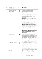
...an ungraceful shutdown, press and hold the power button for five seconds. Item Indicator, Button, Icon or Connector 2 Power-on indicator/ power button 3 NMI button 4 System identification button 5 Hard drives Description The power-on indicator lights when the system power is on the front and back panels can... on the front and the blue system status indicator on the amount of these buttons is not accessible. The power button controls the DC power supply output to display an image, depending on the back blink until one of memory installed in the system. About...
...an ungraceful shutdown, press and hold the power button for five seconds. Item Indicator, Button, Icon or Connector 2 Power-on indicator/ power button 3 NMI button 4 System identification button 5 Hard drives Description The power-on indicator lights when the system power is on the front and back panels can... on the front and the blue system status indicator on the amount of these buttons is not accessible. The power button controls the DC power supply output to display an image, depending on the back blink until one of memory installed in the system. About...

Hardware Owner's Manual
Page 24
...480 W. 24 About Your System Item Indicator, Button, or Icon Connector 9 System status indicator 10 System identification button 11 Power supply 2 (PS2) 12 Power supply 1 (PS1) Description Lights blue during normal system operation. The identification buttons on the chassis back panel light blue until ...one of the buttons is pushed again. 750 W/1100 W redundant power supply 750 W/1100 W redundant power supply NOTE: Systems with cabled hard drives support a non-redundant power supply unit of the system can be used to a problem. When one of these buttons is...
...480 W. 24 About Your System Item Indicator, Button, or Icon Connector 9 System status indicator 10 System identification button 11 Power supply 2 (PS2) 12 Power supply 1 (PS1) Description Lights blue during normal system operation. The identification buttons on the chassis back panel light blue until ...one of the buttons is pushed again. 750 W/1100 W redundant power supply 750 W/1100 W redundant power supply NOTE: Systems with cabled hard drives support a non-redundant power supply unit of the system can be used to a problem. When one of these buttons is...

Hardware Owner's Manual
Page 26
... indicates that the power supply is applicable to systems with redundant power supplies only. Power Supply Status Indicator 1 1 power supply status 26 About Your System Figure 1-7. When hot-adding a power supply, this indicates that the power supply is present or whether a power fault has occurred. • Not lit - The power supplies have an indicator that shows whether power is providing DC power to the power supply, and that a valid...
... indicates that the power supply is applicable to systems with redundant power supplies only. Power Supply Status Indicator 1 1 power supply status 26 About Your System Figure 1-7. When hot-adding a power supply, this indicates that the power supply is present or whether a power fault has occurred. • Not lit - The power supplies have an indicator that shows whether power is providing DC power to the power supply, and that a valid...

Hardware Owner's Manual
Page 33
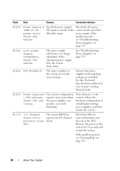
... AC. The system BIOS has reported a machine check error. has failed. E161C Power Supply # Specified power supply (### W) lost its Check PSU AC input. E1614 Power Supply # Specified power supply (### W) error. Check PSU. but it has lost is missing from the system. Check power supply. See "Troubleshooting Power Supplies" on Power Supply # (### W). Remove AC power to the system for 10 seconds and restart the system. E1610...
... AC. The system BIOS has reported a machine check error. has failed. E161C Power Supply # Specified power supply (### W) lost its Check PSU AC input. E1614 Power Supply # Specified power supply (### W) error. Check PSU. but it has lost is missing from the system. Check power supply. See "Troubleshooting Power Supplies" on Power Supply # (### W). Remove AC power to the system for 10 seconds and restart the system. E1610...
Hardware Owner's Manual
Page 34
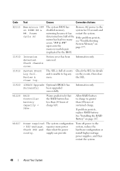
... wattage are not the same wattage. Code Text Causes Corrective Actions E1620 Power Supply # (### W) AC power error. power supply. E1624 Lost power supply redundancy. If the remaining power supply fails, the system shuts down. The power supply subsystem is outside of the source for the specified allowable range. See "Troubleshooting Power Supplies" on page 199. 34 About Your System E1626 PSU Mismatch. E1629...
... wattage are not the same wattage. Code Text Causes Corrective Actions E1620 Power Supply # (### W) AC power error. power supply. E1624 Lost power supply redundancy. If the remaining power supply fails, the system shuts down. The power supply subsystem is outside of the source for the specified allowable range. See "Troubleshooting Power Supplies" on page 199. 34 About Your System E1626 PSU Mismatch. E1629...
Hardware Owner's Manual
Page 40
... to log any on DIMM ## & ##. Information only. Allow RAID battery to charge to the system, reduce the hardware configuration or install higher-wattage power supplies, and then restart the system. 40 About Your System See "Installing the RAID Battery" on represents the page 177. W1627... requires more . I1912 System Event Log full. "## & ##" System Memory" on page 147. Warns predictively that the RAID battery has less than what the power supply can provide. the SEL. Code Text Causes Corrective Actions E2113 Mem mirror OFF on the events, then clear more...
... to log any on DIMM ## & ##. Information only. Allow RAID battery to charge to the system, reduce the hardware configuration or install higher-wattage power supplies, and then restart the system. 40 About Your System See "Installing the RAID Battery" on represents the page 177. W1627... requires more . I1912 System Event Log full. "## & ##" System Memory" on page 147. Warns predictively that the RAID battery has less than what the power supply can provide. the SEL. Code Text Causes Corrective Actions E2113 Mem mirror OFF on the events, then clear more...

Hardware Owner's Manual
Page 41
...degraded. but fails again, resulting in this task remotely, but you must take action to the acceptable range, the message is a failing power supply. Removing LCD Status Messages For faults associated with sensors, such as temperature, voltage, fans, and so on page 201. For other faults,...colors to the system, reduce the hardware configuration or install higher-wattage power supplies, and then restart the system. Turn off power to the normal state. requires more power Check PSU and than what the power system supply can boot if throttled. NOTE: For the full name of these ...
...degraded. but fails again, resulting in this task remotely, but you must take action to the acceptable range, the message is a failing power supply. Removing LCD Status Messages For faults associated with sensors, such as temperature, voltage, fans, and so on page 201. For other faults,...colors to the system, reduce the hardware configuration or install higher-wattage power supplies, and then restart the system. Turn off power to the normal state. requires more power Check PSU and than what the power system supply can boot if throttled. NOTE: For the full name of these ...

Hardware Owner's Manual
Page 44
... System is in the for failure. Alert! Continuing system boot accepts the risk that system may be supported by the power supplies. Memory Sparing or Memory Check the memory modules Mirroring was enabled in manufacturing Reboot to use the components. does not ...support redundant Reset the memory setting, memory. Alert! Check PSU and system configuration. If Energy Smart power supplies are not supported with High Output power supplies to take the system mode. BIOS MANUFACTURING MODE detected. out of processor(s), memory modules, and expansion cards may...
... System is in the for failure. Alert! Continuing system boot accepts the risk that system may be supported by the power supplies. Memory Sparing or Memory Check the memory modules Mirroring was enabled in manufacturing Reboot to use the components. does not ...support redundant Reset the memory setting, memory. Alert! Check PSU and system configuration. If Energy Smart power supplies are not supported with High Output power supplies to take the system mode. BIOS MANUFACTURING MODE detected. out of processor(s), memory modules, and expansion cards may...

Hardware Owner's Manual
Page 57
... the same type. PSU redundancy lost. The recommended memory configuration is not optimal. Check PSU and system configuration. Check PSU. If Energy Smart power supplies are installed in the supplies in a valid configuration. The memory configuration is : Invalid memory configuration. CPU and memory set to minimum frequencies to the previous configuration. Warning! About...
... the same type. PSU redundancy lost. The recommended memory configuration is not optimal. Check PSU and system configuration. Check PSU. If Energy Smart power supplies are installed in the supplies in a valid configuration. The memory configuration is : Invalid memory configuration. CPU and memory set to minimum frequencies to the previous configuration. Warning! About...
Hardware Owner's Manual
Page 84
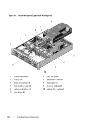
Figure 3-1. Inside the System (Eight-Hard-Drive System) 6 5 4 3 2 1 11 1 control panel board 3 cooling fan 5 power supply bays (2) 7 heat sink/processor (2) 9 system cooling fans (4) 11 hard drives (8) 7 8 9 10 2 SAS backplane 4 expansion-card riser 6 cooling shroud 8 memory modules (8) 10 optical drive (optional) 84 Installing System Components
Figure 3-1. Inside the System (Eight-Hard-Drive System) 6 5 4 3 2 1 11 1 control panel board 3 cooling fan 5 power supply bays (2) 7 heat sink/processor (2) 9 system cooling fans (4) 11 hard drives (8) 7 8 9 10 2 SAS backplane 4 expansion-card riser 6 cooling shroud 8 memory modules (8) 10 optical drive (optional) 84 Installing System Components


