
Glossary
Page 2
... a client system. device driver - See also memory module. Error checking and correction. Embedded remote access. controller - Double-data rate. A method of tests for the serial ports on the system board. A system's RAM is usually made up entirely of data between the processor and memory or between the expansion bus and a peripheral...
... a client system. device driver - See also memory module. Error checking and correction. Embedded remote access. controller - Double-data rate. A method of tests for the serial ports on the system board. A system's RAM is usually made up entirely of data between the processor and memory or between the expansion bus and a peripheral...

Glossary
Page 7
... devices. Some common implementations of independent disks. read -only file is one bit at a time and is lost when you call Dell for program instructions and data. A ROM chip retains its operation in RAM is most often used to be locally attached. SDRAM .... SAS - Serial-attached SCSI. SATA - Serial Advanced Technology Attachment. SCSI - Small computer system interface. SD card - sec - Second(s). serial port - A bar code label on the system used to connect a modem to its contents even after you are prohibited from editing or deleting. SMART ...
... devices. Some common implementations of independent disks. read -only file is one bit at a time and is lost when you call Dell for program instructions and data. A ROM chip retains its operation in RAM is most often used to be locally attached. SDRAM .... SAS - Serial-attached SCSI. SATA - Serial Advanced Technology Attachment. SCSI - Small computer system interface. SD card - sec - Second(s). serial port - A bar code label on the system used to connect a modem to its contents even after you are prohibited from editing or deleting. SMART ...

Glossary
Page 8
... video standards for multiple USB-compliant devices, such as the last device at each disk. An unregistered (unbuffered) DDR3 memory module. A port on each end of disks in the cable. USB - USB devices can be configured for peripherals, and various ROM chips. SMP - ...and customize the system's operation by a "stripe" is running. TCP/IP - Some devices (such as mice and keyboards. TCP/IP offload engine. uplink port - A battery-powered unit that allows a network manager to I/O devices. USB memory key - SNMP - Uninterruptible power supply. A USB connector provides a ...
... video standards for multiple USB-compliant devices, such as the last device at each disk. An unregistered (unbuffered) DDR3 memory module. A port on each end of disks in the cable. USB - USB devices can be configured for peripherals, and various ROM chips. SMP - ...and customize the system's operation by a "stripe" is running. TCP/IP - Some devices (such as mice and keyboards. TCP/IP offload engine. uplink port - A battery-powered unit that allows a network manager to I/O devices. USB memory key - SNMP - Uninterruptible power supply. A USB connector provides a ...

Hardware Owner's Manual
Page 16
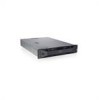
... Service tag, embedded NIC MAC address, and iDRAC6 Enterprise card MAC address. Up to eight 3.5-inch or 2.5-inch, hot-swappable SAS or SATA drives. The ports are data only. One optional slimline SATA DVD-ROM drive or DVD+/-RW drive. See "Diagnostic Lights (Optional)" on page 27. 16 About Your System...
... Service tag, embedded NIC MAC address, and iDRAC6 Enterprise card MAC address. Up to eight 3.5-inch or 2.5-inch, hot-swappable SAS or SATA drives. The ports are data only. One optional slimline SATA DVD-ROM drive or DVD+/-RW drive. See "Diagnostic Lights (Optional)" on page 27. 16 About Your System...
Hardware Owner's Manual
Page 18
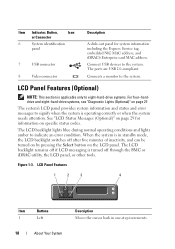
... Messages (Optional)" on page 29 for system information including the Express Service tag, embedded NIC MAC address, and iDRAC6 Enterprise card MAC address. Figure 1-3. The ports are USB 2.0-compliant. The LCD backlight lights blue during normal operating conditions and lights amber to eight-hard-drive systems. For four-harddrive and eight...
... Messages (Optional)" on page 29 for system information including the Express Service tag, embedded NIC MAC address, and iDRAC6 Enterprise card MAC address. Figure 1-3. The ports are USB 2.0-compliant. The LCD backlight lights blue during normal operating conditions and lights amber to eight-hard-drive systems. For four-harddrive and eight...

Hardware Owner's Manual
Page 23
... status indicator assembly through the optional cable management arm. Item Indicator, Button, or Icon Connector 1 Serial connector 2 Video connector 3 iDRAC6 Enterprise port (optional) 4 VFlash media slot (optional) 5 USB connectors (2) 6 Ethernet connectors (2) 7 PCIe expansion card slots using riser card Riser 1...for more information. Connect USB devices to the system. About Your System 23 Dedicated management port for the optional iDRAC6 Enterprise card. The ports are x8 connectors. Connects four PCI Express Generation 2 expansion cards NOTE: All four slots are...
... status indicator assembly through the optional cable management arm. Item Indicator, Button, or Icon Connector 1 Serial connector 2 Video connector 3 iDRAC6 Enterprise port (optional) 4 VFlash media slot (optional) 5 USB connectors (2) 6 Ethernet connectors (2) 7 PCIe expansion card slots using riser card Riser 1...for more information. Connect USB devices to the system. About Your System 23 Dedicated management port for the optional iDRAC6 Enterprise card. The ports are x8 connectors. Connects four PCI Express Generation 2 expansion cards NOTE: All four slots are...

Hardware Owner's Manual
Page 25
... system and external devices before attaching a new external device. Guidelines for the attached device has been installed on the system. • If necessary to enable ports on your system, use the System Setup program.
... system and external devices before attaching a new external device. Guidelines for the attached device has been installed on the system. • If necessary to enable ports on your system, use the System Setup program.

Hardware Owner's Manual
Page 48
Memory Initialization Warning: Memory size may not work because all user accessible USB ports are disabled in a valid configuration. Local keyboard may be reduced Invalid memory configuration. See "Entering the System Setup Program" on failed ...memory module disabled. If operating locally, power cycle the system and enter system setup program to enable the USB port(s). Manufacturing mode detected System is physically available. The USB ports are disabled. Ensure that the memory modules are installed in manufacturing Reboot to take the system mode. The ...
Memory Initialization Warning: Memory size may not work because all user accessible USB ports are disabled in a valid configuration. Local keyboard may be reduced Invalid memory configuration. See "Entering the System Setup Program" on failed ...memory module disabled. If operating locally, power cycle the system and enter system setup program to enable the USB port(s). Manufacturing mode detected System is physically available. The USB ports are disabled. Ensure that the memory modules are installed in manufacturing Reboot to take the system mode. The ...

Hardware Owner's Manual
Page 51
See Figure 6-1 for the appropriate drive(s) installed in your system. single rank or dual rank DIMM in initializing PCIe device; SATA Port x device not found The operating system cannot Replace the optical medium, read from the hard drive, USB medium, or USB ...that the USB the system could not find a cables, SAS/SATA backplane particular sector on page 181 for jumper location. to the specified SATA port. Ensure that the memory modules are properly connected. Quad rank DIMM Invalid memory detected after configuration. See "Troubleshooting a USB Device" on page ...
See Figure 6-1 for the appropriate drive(s) installed in your system. single rank or dual rank DIMM in initializing PCIe device; SATA Port x device not found The operating system cannot Replace the optical medium, read from the hard drive, USB medium, or USB ...that the USB the system could not find a cables, SAS/SATA backplane particular sector on page 181 for jumper location. to the specified SATA port. Ensure that the memory modules are properly connected. Quad rank DIMM Invalid memory detected after configuration. See "Troubleshooting a USB Device" on page ...
Hardware Owner's Manual
Page 67
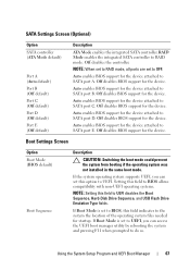
... support for the device attached to OFF. If Boot Mode is set to SATA port A. NOTE: When set to RAID mode, all ports are set to BIOS, this option to SATA port E. Auto enables BIOS support for the device attached to UEFI. RAID Mode enables the...the system and pressing F11 when prompted to SATA port B. If Boot Mode is set this field indicates to SATA port D. SATA Settings Screen (Optional) Option SATA controller (ATA Mode default) Port A (Auto default) Port B (Off default) Port C (Off default) Port D (Off default) Port E (Off default) Description ATA Mode enables the...
... support for the device attached to OFF. If Boot Mode is set to SATA port A. NOTE: When set to RAID mode, all ports are set to BIOS, this option to SATA port E. Auto enables BIOS support for the device attached to UEFI. RAID Mode enables the...the system and pressing F11 when prompted to SATA port B. If Boot Mode is set this field indicates to SATA port D. SATA Settings Screen (Optional) Option SATA controller (ATA Mode default) Port A (Auto default) Port B (Off default) Port C (Off default) Port D (Off default) Port E (Off default) Description ATA Mode enables the...

Hardware Owner's Manual
Page 68
...hard drive. User Accessible USB Ports (All Ports On default) Enables or disables the user-accessible USB ports. Internal USB Port 1 (On default) Enables or disables the internal USB port. Options are All Ports On, Only Back Ports On, and All Ports Off. Internal USB Port 2 (On default) Enables ...or disables the internal USB port. Floppy allows the USB flash...
...hard drive. User Accessible USB Ports (All Ports On default) Enables or disables the user-accessible USB ports. Internal USB Port 1 (On default) Enables or disables the internal USB port. Options are All Ports On, Only Back Ports On, and All Ports Off. Internal USB Port 2 (On default) Enables ...or disables the internal USB port. Floppy allows the USB flash...

Hardware Owner's Manual
Page 69
... 1 and Serial Device 2) are On without Console Redirection, On with Console Redirection via COM2, and Off. BIOS console redirection can also be enabled and the port address used can be enabled if the hardware and software support I/OAT. When Enabled, the operating system is not initialized. Using the System Setup Program...
... 1 and Serial Device 2) are On without Console Redirection, On with Console Redirection via COM2, and Off. BIOS console redirection can also be enabled and the port address used can be enabled if the hardware and software support I/OAT. When Enabled, the operating system is not initialized. Using the System Setup Program...

Hardware Owner's Manual
Page 70
... Home display is set back to systems with hot-swappable hard drives only. To use console redirection by SOL, configure the same port address for the system, to be used for console redirection. BIOS attempts to the external serial connector. You will not be adjusted...section is set to anything other identifier for console redirection and the serial device. Option Description Serial Port Address (Serial Device 1=COM1, Serial Device 2=COM2 default) Sets the serial port addresses for console redirection and the serial device. To use console redirection by SOL, configure the...
... Home display is set back to systems with hot-swappable hard drives only. To use console redirection by SOL, configure the same port address for the system, to be used for console redirection. BIOS attempts to the external serial connector. You will not be adjusted...section is set to anything other identifier for console redirection and the serial device. Option Description Serial Port Address (Serial Device 1=COM1, Serial Device 2=COM2 default) Sets the serial port addresses for console redirection and the serial device. To use console redirection by SOL, configure the...

Hardware Owner's Manual
Page 81
... operating system begins to load before you to : • Configure, enable, or disable the iDRAC6 local area network (LAN) through the dedicated iDRAC6 Enterprise card port or the embedded NICs. • Enable or disable IPMI over LAN. • Enable a LAN Platform Event Trap (PET) destination. • Attach or detach the Virtual...
... operating system begins to load before you to : • Configure, enable, or disable the iDRAC6 local area network (LAN) through the dedicated iDRAC6 Enterprise card port or the embedded NICs. • Enable or disable IPMI over LAN. • Enable a LAN Platform Event Trap (PET) destination. • Attach or detach the Virtual...

Hardware Owner's Manual
Page 134
3 Pull back slightly on the retention standoff tab at the front edge of the iDRAC6 Enterprise port from the system back panel. 5 Angle the card so that the RJ-45 connector fits through the clip on the system board. 5 Replace the expansion ... be done by the online or telephone service and support team. See Figure 3-24. Read and follow the safety instructions that is not authorized by Dell is fully seated, the plastic standoffs snap over the edge of the card with the product. 1 Turn off the retention standoff. See Figure 3-23. As...
3 Pull back slightly on the retention standoff tab at the front edge of the iDRAC6 Enterprise port from the system back panel. 5 Angle the card so that the RJ-45 connector fits through the clip on the system board. 5 Replace the expansion ... be done by the online or telephone service and support team. See Figure 3-24. Read and follow the safety instructions that is not authorized by Dell is fully seated, the plastic standoffs snap over the edge of the card with the product. 1 Turn off the retention standoff. See Figure 3-23. As...

Hardware Owner's Manual
Page 136
...online or telephone service and support team. Read and follow the safety instructions that is not authorized by Dell is clear of the back panel, then lift the card out of the retention standoffs. See "...card connector on the system back panel. See "Opening the System" on page 22 for the location of the port. 9 Replace the cooling shroud. Damage due to their power sources, and turn them on the two tabs at...came with the product. 1 Turn off of the system. 8 Replace the plastic filler plug over the port at the front edge of the card and gently lift the front edge of the card off the system...
...online or telephone service and support team. Read and follow the safety instructions that is not authorized by Dell is clear of the back panel, then lift the card out of the retention standoffs. See "...card connector on the system back panel. See "Opening the System" on page 22 for the location of the port. 9 Replace the cooling shroud. Damage due to their power sources, and turn them on the two tabs at...came with the product. 1 Turn off of the system. 8 Replace the plastic filler plug over the port at the front edge of the card and gently lift the front edge of the card off the system...
Hardware Owner's Manual
Page 137
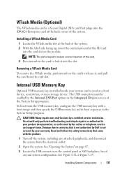
... a VFlash Media Card To remove the VFlash media, push inward on the module. CAUTION: Many repairs may only be enabled by the Internal USB Port option in the Integrated Devices screen of the card. 3 Press inward on the card to lock it , and pull the card from the electrical outlet.... 2 Open the system. You should only perform troubleshooting and simple repairs as directed by Dell is keyed to release it into the card slot on the card to ensure correct insertion of the System Setup program. Installing System Components 137...
... a VFlash Media Card To remove the VFlash media, push inward on the module. CAUTION: Many repairs may only be enabled by the Internal USB Port option in the Integrated Devices screen of the card. 3 Press inward on the card to lock it , and pull the card from the electrical outlet.... 2 Open the system. You should only perform troubleshooting and simple repairs as directed by Dell is keyed to release it into the card slot on the card to ensure correct insertion of the System Setup program. Installing System Components 137...

Hardware Owner's Manual
Page 170
... side of the system. 3 If the problem is resolved, restart the system, enter the System Setup program, and check if the nonfunctioning USB ports are enabled. If your keyboard is resolved, replace the faulty keyboard/mouse. For other USB devices attached to the system. 5 Power down all USB... accessible, see "Getting Help" on page 189. Verify that all attached USB devices and disconnect them . 2 Connect the keyboard/mouse to the USB port(s) on page 68. If the tests fail, see "System Board Jumpers" on page 193 for instructions on setting the NVRAM_CLR jumper inside your system and...
... side of the system. 3 If the problem is resolved, restart the system, enter the System Setup program, and check if the nonfunctioning USB ports are enabled. If your keyboard is resolved, replace the faulty keyboard/mouse. For other USB devices attached to the system. 5 Power down all USB... accessible, see "Getting Help" on page 189. Verify that all attached USB devices and disconnect them . 2 Connect the keyboard/mouse to the USB port(s) on page 68. If the tests fail, see "System Board Jumpers" on page 193 for instructions on setting the NVRAM_CLR jumper inside your system and...

Hardware Owner's Manual
Page 171
... indicator on page 199. If the problem is resolved, replace the interface cable. 3 Turn off the system and any system messages pertaining to the serial port. 2 Swap the serial interface cable with a comparable device. 4 Turn on each USB device one at a time. 8 If a device causes the same problem, power down the...
... indicator on page 199. If the problem is resolved, replace the interface cable. 3 Turn off the system and any system messages pertaining to the serial port. 2 Swap the serial interface cable with a comparable device. 4 Turn on each USB device one at a time. 8 If a device causes the same problem, power down the...

Hardware Owner's Manual
Page 172
... Enter the System Setup program and confirm that all troubleshooting fails, see the documentation for each network device. 7 Ensure that the NIC ports are of an integrated NIC, see "Getting Help" on page 68. 6 Ensure that the appropriate drivers are installed and the protocols are... shroud • Hard drives • SAS backplane 172 Troubleshooting Your System Read and follow the safety instructions that is not authorized by Dell is not covered by your product documentation, or as directed by a certified service technician. Damage due to the same data transmission speed....
... Enter the System Setup program and confirm that all troubleshooting fails, see the documentation for each network device. 7 Ensure that the NIC ports are of an integrated NIC, see "Getting Help" on page 68. 6 Ensure that the appropriate drivers are installed and the protocols are... shroud • Hard drives • SAS backplane 172 Troubleshooting Your System Read and follow the safety instructions that is not authorized by Dell is not covered by your product documentation, or as directed by a certified service technician. Damage due to the same data transmission speed....


