
Glossary
Page 2
...-in -line memory module. controller - A chip or expansion card that allows the operating system or some specialized function to communicate with a peripheral. Direct current. DRAM - Error checking and correction. Electromagnetic interference. ESM - control panel - Central processing unit. DDR - Double-data rate. device driver - A method of automatically assigning an IP address to...
...-in -line memory module. controller - A chip or expansion card that allows the operating system or some specialized function to communicate with a peripheral. Direct current. DRAM - Error checking and correction. Electromagnetic interference. ESM - control panel - Central processing unit. DDR - Double-data rate. device driver - A method of automatically assigning an IP address to...

Glossary
Page 6
...of sources. NMI - A device sends an NMI to run on your system. You must usually be revised to signal the processor about hardware errors. POST - Before the operating system loads when you turn on another processor. provider - PXE - ns - Nonvolatile random-access memory. parity...turn off your system, the POST tests various system components such as a diskette drive or keyboard, connected to create an image. PowerEdge RAID controller. Power-on a video display. Preboot eXecution Environment. Memory that communicates with a block of pixels up and down. partition...
...of sources. NMI - A device sends an NMI to run on your system. You must usually be revised to signal the processor about hardware errors. POST - Before the operating system loads when you turn on another processor. provider - PXE - ns - Nonvolatile random-access memory. parity...turn off your system, the POST tests various system components such as a diskette drive or keyboard, connected to create an image. PowerEdge RAID controller. Power-on a video display. Preboot eXecution Environment. Memory that communicates with a block of pixels up and down. partition...

Glossary
Page 7
... in ROM code. R-DIMM - Read-only memory. RAID on the system used to connect a modem to its contents even after you call Dell for program instructions and data. SATA - Small computer system interface. A legacy I /O bus interface with a 9-pin connector that transfers data... storage area for technical support. Secure digital flash memory card. Self-Monitoring Analysis and Reporting Technology. Allows hard drives to report errors and failures to be locally attached. Your system contains some programs essential to the system. A bar code label on motherboard. ...
... in ROM code. R-DIMM - Read-only memory. RAID on the system used to connect a modem to its contents even after you call Dell for program instructions and data. SATA - Small computer system interface. A legacy I /O bus interface with a 9-pin connector that transfers data... storage area for technical support. Secure digital flash memory card. Self-Monitoring Analysis and Reporting Technology. Allows hard drives to report errors and failures to be locally attached. Your system contains some programs essential to the system. A bar code label on motherboard. ...

Information Update
Page 1
August 2010 The error event E1812 is logged in the System Event Log (SEL) when the internal hard drives are removed. System Event Log Update In twelve-hard-drive ...
August 2010 The error event E1812 is logged in the System Event Log (SEL) when the internal hard drives are removed. System Event Log Update In twelve-hard-drive ...

Getting Started Guide
Page 11
...-rank DIMMs) 64 GB (8 GB dual- and quad-rank DIMMs) Getting Started With Your System 9 Memory Architecture 1066 or 1333 MHz DDR3 registered or unbuffered Error Correcting Code (ECC) DIMMs Memory module sockets Eight 240-pin Memory module capacities Four-hard-drive systems Eight-hard-drive systems Twelve-hard-drive systems...
...-rank DIMMs) 64 GB (8 GB dual- and quad-rank DIMMs) Getting Started With Your System 9 Memory Architecture 1066 or 1333 MHz DDR3 registered or unbuffered Error Correcting Code (ECC) DIMMs Memory module sockets Eight 240-pin Memory module capacities Four-hard-drive systems Eight-hard-drive systems Twelve-hard-drive systems...

Hardware Owner's Manual
Page 4
... 60 2 Using the System Setup Program and UEFI Boot Manager 61 Choosing the System Boot Mode 61 Entering the System Setup Program 62 Responding to Error Messages 62 Using the System Setup Program Navigation Keys 62 System Setup Options 63 Main Screen 63 Memory Settings Screen 65 Processor Settings Screen 66...
... 60 2 Using the System Setup Program and UEFI Boot Manager 61 Choosing the System Boot Mode 61 Entering the System Setup Program 62 Responding to Error Messages 62 Using the System Setup Program Navigation Keys 62 System Setup Options 63 Main Screen 63 Memory Settings Screen 65 Processor Settings Screen 66...
Hardware Owner's Manual
Page 15
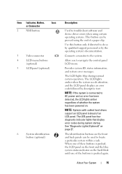
...lights amber when the system needs attention, and the LCD panel displays an error code followed by the operating system's documentation. The LED panel has four diagnostic indicator lights that display error codes during normal system operation. The LCD lights blue during system startup. ...Provides system ID, status information, and system error messages. The identification buttons on . Use this button only if directed to troubleshoot software and device driver errors when using certain operating systems. This button can be pressed using the end...
...lights amber when the system needs attention, and the LCD panel displays an error code followed by the operating system's documentation. The LED panel has four diagnostic indicator lights that display error codes during normal system operation. The LCD lights blue during system startup. ...Provides system ID, status information, and system error messages. The identification buttons on . Use this button only if directed to troubleshoot software and device driver errors when using certain operating systems. This button can be pressed using the end...

Hardware Owner's Manual
Page 16
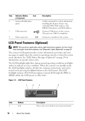
... (Twelve-Hard-Drive System) 2 34 5 1 6 78 Item Indicator, Button, Icon or Connector 1 LED panel Description The LED panel has four diagnostic indicator lights that display error codes during system startup. Figure 1-2. See "Diagnostic Lights (Optional)" on page 27. 16 About Your System A slide-out panel for system information including the Express...
... (Twelve-Hard-Drive System) 2 34 5 1 6 78 Item Indicator, Button, Icon or Connector 1 LED panel Description The LED panel has four diagnostic indicator lights that display error codes during system startup. Figure 1-2. See "Diagnostic Lights (Optional)" on page 27. 16 About Your System A slide-out panel for system information including the Express...
Hardware Owner's Manual
Page 17
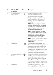
... systems, turning off . NOTE: To force an ungraceful shutdown, press and hold the power button for five seconds. Used to troubleshoot software and device driver errors when using certain operating systems. This button can be used to display an image, depending on the amount of a paper clip. Item Indicator, Button, Icon...
... systems, turning off . NOTE: To force an ungraceful shutdown, press and hold the power button for five seconds. Used to troubleshoot software and device driver errors when using certain operating systems. This button can be used to display an image, depending on the amount of a paper clip. Item Indicator, Button, Icon...
Hardware Owner's Manual
Page 18
..., embedded NIC MAC address, and iDRAC6 Enterprise card MAC address. Connects a monitor to the system. The system's LCD panel provides system information and status and error messages to signify when the system is turned off if LCD messaging is operating correctly or when the system needs attention. When the system is...
..., embedded NIC MAC address, and iDRAC6 Enterprise card MAC address. Connects a monitor to the system. The system's LCD panel provides system information and status and error messages to signify when the system is turned off if LCD messaging is operating correctly or when the system needs attention. When the system is...
Hardware Owner's Manual
Page 19
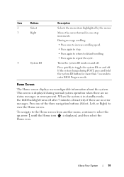
... Home screen. If the system hangs during normal system operation when there are no status messages or errors present. Press one -step increments. This screen is in one of inactivity if there are no error messages. Turns the system ID mode on and off after 5 minutes of the three navigation buttons (Select...
... Home screen. If the system hangs during normal system operation when there are no status messages or errors present. Press one -step increments. This screen is in one of inactivity if there are no error messages. Turns the system ID mode on and off after 5 minutes of the three navigation buttons (Select...

Hardware Owner's Manual
Page 20
...Name Displays the name of messages in this format. Select Setup DNS to enable DNS installed on the LCD Home screen. Set error Select SEL to display LCD error messages in a format that can be selected to view domain addresses. Set home Select the default information to be displayed on the...Asset tag or the Service tag for the optional iDRAC6. Setup Menu Option Description BMC or DRAC Select DHCP or Static IP to display LCD error messages in the SEL. See "LCD Status Messages (Optional)" on the Home screen. NOTE: If the iDRAC6 Express card is not installed on...
...Name Displays the name of messages in this format. Select Setup DNS to enable DNS installed on the LCD Home screen. Set error Select SEL to display LCD error messages in a format that can be selected to view domain addresses. Set home Select the default information to be displayed on the...Asset tag or the Service tag for the optional iDRAC6. Setup Menu Option Description BMC or DRAC Select DHCP or Static IP to display LCD error messages in the SEL. See "LCD Status Messages (Optional)" on the Home screen. NOTE: If the iDRAC6 Express card is not installed on...
Hardware Owner's Manual
Page 27
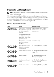
... are not lit after POST. See "Troubleshooting Processors" on page 177. See "Troubleshooting System Memory" on page 186. Cards" on the system front panel display error codes during system startup. Diagnostic Lights (Optional) NOTE: This section is in recovery mode. Table 1-1 lists the causes and possible corrective actions associated with cabled...
... are not lit after POST. See "Troubleshooting Processors" on page 177. See "Troubleshooting System Memory" on page 186. Cards" on the system front panel display error codes during system startup. Diagnostic Lights (Optional) NOTE: This section is in recovery mode. Table 1-1 lists the causes and possible corrective actions associated with cabled...

Hardware Owner's Manual
Page 28
... system board hardware failure. Other failure. If the problem persists, see "Getting Help" on page 199. System board failure. Memory configuration See "Troubleshooting System error. page 199. See "Getting Help" on page 199. 28 About Your System See "Troubleshooting System Memory" on page 199. See "Getting Help" on... installed in your system. No memory modules detected. Possible USB failure. See "Troubleshooting Your System" on page 169 for information on configuration error. Possible system resource See "Contacting Dell" on the drives installed in your system.
... system board hardware failure. Other failure. If the problem persists, see "Getting Help" on page 199. System board failure. Memory configuration See "Troubleshooting System error. page 199. See "Getting Help" on page 199. 28 About Your System See "Troubleshooting System Memory" on page 199. See "Getting Help" on... installed in your system. No memory modules detected. Possible USB failure. See "Troubleshooting Your System" on page 169 for information on configuration error. Possible system resource See "Contacting Dell" on the drives installed in your system.
Hardware Owner's Manual
Page 29
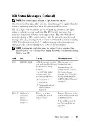
... blue to indicate a normal operating condition, and lights amber to boot, press the System ID button for at least five seconds until an error code appears on the LCD. For information on page 199. Record the code, then see "Getting Help" on the SEL and configuring system...Contact support. in the system event log (SEL). See "Using the following conditions: System Setup Program • The system is off and active errors are displayed. The LCD messages refer to events recorded in the System Setup program. Remove AC power to the system for critical failure events. Causes...
... blue to indicate a normal operating condition, and lights amber to boot, press the System ID button for at least five seconds until an error code appears on the LCD. For information on page 199. Record the code, then see "Getting Help" on the SEL and configuring system...Contact support. in the system event log (SEL). See "Using the following conditions: System Setup Program • The system is off and active errors are displayed. The LCD messages refer to events recorded in the System Setup program. Remove AC power to the system for critical failure events. Causes...

Hardware Owner's Manual
Page 32
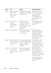
...your system's Getting Started Guide. Power has reported a processor cycle AC. Code Text Causes Corrective Actions E1410 System Fatal Error detected. Specified processor has an Remove AC power to the type described in the processor technical specifications outlined in an unsupported configuration. The... error system for 10 seconds and restart the system. Ensure that the processor heat sinks are in an CPU config. Specified...
...your system's Getting Started Guide. Power has reported a processor cycle AC. Code Text Causes Corrective Actions E1410 System Fatal Error detected. Specified processor has an Remove AC power to the type described in the processor technical specifications outlined in an unsupported configuration. The... error system for 10 seconds and restart the system. Ensure that the processor heat sinks are in an CPU config. Specified...

Hardware Owner's Manual
Page 33
...from the system. cables. Check the AC power source for 10 seconds and restart the system. E1610 Power Supply # (### W) missing. parity error. Remove AC power to the system for 10 seconds and restart the system. If the problem persists, see "Getting Help" on page 175.... supply (### W) lost its Check PSU AC input. Code Text Causes Corrective Actions E1420 CPU Bus parity The system BIOS has error. E1422 CPU # machine check error. If the problem persists, see "Troubleshooting Power Supplies" on page 175. Specified power supply was removed or is attached to the...
...from the system. cables. Check the AC power source for 10 seconds and restart the system. E1610 Power Supply # (### W) missing. parity error. Remove AC power to the system for 10 seconds and restart the system. If the problem persists, see "Getting Help" on page 175.... supply (### W) lost its Check PSU AC input. Code Text Causes Corrective Actions E1420 CPU Bus parity The system BIOS has error. E1422 CPU # machine check error. If the problem persists, see "Troubleshooting Power Supplies" on page 175. Specified power supply was removed or is attached to the...
Hardware Owner's Manual
Page 34
... matching wattage are not the same wattage. Ensure that power supplies with throttling. Check PSU and config. The system BIOS has reported an I /O channel check error. If the problem persists, see "Getting Help" on page 175. If the problem persists, see "Troubleshooting Power Supplies" on page 199. 34 About Your ... reduce the hardware configuration or install higher-wattage power supplies, and then restart the system. Code Text Causes Corrective Actions E1620 Power Supply # (### W) AC power error. See "Troubleshooting Power Supplies" on page 175. Check PSU cables.
... matching wattage are not the same wattage. Ensure that power supplies with throttling. Check PSU and config. The system BIOS has reported an I /O channel check error. If the problem persists, see "Getting Help" on page 175. If the problem persists, see "Troubleshooting Power Supplies" on page 199. 34 About Your ... reduce the hardware configuration or install higher-wattage power supplies, and then restart the system. Code Text Causes Corrective Actions E1620 Power Supply # (### W) AC power error. See "Troubleshooting Power Supplies" on page 175. Check PSU cables.
Hardware Owner's Manual
Page 35
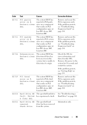
...Remove AC power to determine its origin. If the problem persists, see "Troubleshooting Expansion Cards" on page 184. E1714 Unknown error. E171F PCI fatal error on #. Review & clear SEL. Corrective Actions Remove and reseat the PCIe expansion cards. See "Troubleshooting a Hard Drive"...drive ## The specified hard drive fault. Review has experienced a fault. & clear SEL. Information only. Review & clear SEL. been an error in PCI configuration space at bus ##, device ##, function ##. If the problem persists, see "Troubleshooting Expansion Cards" on page 199. from the...
...Remove AC power to determine its origin. If the problem persists, see "Troubleshooting Expansion Cards" on page 184. E1714 Unknown error. E171F PCI fatal error on #. Review & clear SEL. Corrective Actions Remove and reseat the PCIe expansion cards. See "Troubleshooting a Hard Drive"...drive ## The specified hard drive fault. Review has experienced a fault. & clear SEL. Information only. Review & clear SEL. been an error in PCI configuration space at bus ##, device ##, function ##. If the problem persists, see "Troubleshooting Expansion Cards" on page 199. from the...

Hardware Owner's Manual
Page 36
..." on page 177. See "Troubleshooting System Memory" on page 177. 36 About Your System See "Troubleshooting System Memory" on page 177. E1A15 SAS cable B failure. Error detected during memory configuration. Inspect DIMMs. Install memory or reseat memory modules. E2011 Memory configuration failure. Reseat the cable. Check connection. E2012 Memory Memory configured...
..." on page 177. See "Troubleshooting System Memory" on page 177. 36 About Your System See "Troubleshooting System Memory" on page 177. E1A15 SAS cable B failure. Error detected during memory configuration. Inspect DIMMs. Install memory or reseat memory modules. E2011 Memory configuration failure. Reseat the cable. Check connection. E2012 Memory Memory configured...


