
Glossary
Page 8
...by changing jumper or switch settings on each processor has equal access to I/O devices. SVGA - system configuration information - See RAM. TOE - uplink port - USB memory key - Disk striping writes data across three or more processors connected via a high-bandwidth link and managed by a "stripe" is installed and... - system board - As the main circuit board, the system board usually contains most of an electrical failure. TCP/IP - U-DIMM - A port on each end of the space on the devices or by setting features such as the last device at each disk used to connect to...
...by changing jumper or switch settings on each processor has equal access to I/O devices. SVGA - system configuration information - See RAM. TOE - uplink port - USB memory key - Disk striping writes data across three or more processors connected via a high-bandwidth link and managed by a "stripe" is installed and... - system board - As the main circuit board, the system board usually contains most of an electrical failure. TCP/IP - U-DIMM - A port on each end of the space on the devices or by setting features such as the last device at each disk used to connect to...

Hardware Owner's Manual
Page 16
The ports are data only. A slide-out panel for system information including the Express Service tag, embedded NIC MAC address, and iDRAC6 Enterprise card MAC address. NOTE: DVD devices are USB 2.0-compliant. Up to the system. Figure 1-2. See "Diagnostic Lights (Optional)" on page 27. 16 About ... startup. One optional slimline SATA DVD-ROM drive or DVD+/-RW drive. Item Indicator, Button, Icon or Connector 7 USB connectors (2) 8 Hard drives Four-hard-drive systems Eight-hard-drive systems 9 System identification panel 10 Optical drive (optional) Description Connect...
The ports are data only. A slide-out panel for system information including the Express Service tag, embedded NIC MAC address, and iDRAC6 Enterprise card MAC address. NOTE: DVD devices are USB 2.0-compliant. Up to the system. Figure 1-2. See "Diagnostic Lights (Optional)" on page 27. 16 About ... startup. One optional slimline SATA DVD-ROM drive or DVD+/-RW drive. Item Indicator, Button, Icon or Connector 7 USB connectors (2) 8 Hard drives Four-hard-drive systems Eight-hard-drive systems 9 System identification panel 10 Optical drive (optional) Description Connect...
Hardware Owner's Manual
Page 18
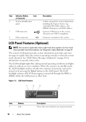
... the BMC or iDRAC utility, the LCD panel, or other tools. The ports are USB 2.0-compliant. Item Indicator, Button, Icon or Connector 6 System identification panel 7 USB connector 8 Video connector Description A slide-out panel for information on specific status codes. Connect USB devices to signify when the system is turned off after five minutes of...
... the BMC or iDRAC utility, the LCD panel, or other tools. The ports are USB 2.0-compliant. Item Indicator, Button, Icon or Connector 6 System identification panel 7 USB connector 8 Video connector Description A slide-out panel for information on specific status codes. Connect USB devices to signify when the system is turned off after five minutes of...

Hardware Owner's Manual
Page 23
...have either riser 1 or riser 2. The ports are x8 connectors. Embedded 10/100/1000 NIC connectors. Connects four PCI Express Generation 2 expansion cards NOTE: All four slots are USB 2.0-compliant. Connects the optional system status indicator ... PCI Express Generation 2 expansion cards. Dedicated management port for the optional iDRAC6 Enterprise card. Item Indicator, Button, or Icon Connector 1 Serial connector 2 Video connector 3 iDRAC6 Enterprise port (optional) 4 VFlash media slot (optional) 5 USB connectors (2) 6 Ethernet connectors (2) 7 PCIe expansion...
...have either riser 1 or riser 2. The ports are x8 connectors. Embedded 10/100/1000 NIC connectors. Connects four PCI Express Generation 2 expansion cards NOTE: All four slots are USB 2.0-compliant. Connects the optional system status indicator ... PCI Express Generation 2 expansion cards. Dedicated management port for the optional iDRAC6 Enterprise card. Item Indicator, Button, or Icon Connector 1 Serial connector 2 Video connector 3 iDRAC6 Enterprise port (optional) 4 VFlash media slot (optional) 5 USB connectors (2) 6 Ethernet connectors (2) 7 PCIe expansion...

Hardware Owner's Manual
Page 48
... System is physically available. out of manufacturing mode. Memory Initialization Warning: Memory size may not work because all user accessible USB ports are disabled in a valid configuration. Local keyboard may be reduced Invalid memory configuration. Ensure that the memory modules are installed... to take the system mode. If operating locally, power cycle the system and enter system setup program to enable the USB port(s). The system runs but with the specified memory module disabled. Message Causes Corrective Actions Keyboard fuse has Overcurrent detected at ...
... System is physically available. out of manufacturing mode. Memory Initialization Warning: Memory size may not work because all user accessible USB ports are disabled in a valid configuration. Local keyboard may be reduced Invalid memory configuration. Ensure that the memory modules are installed... to take the system mode. If operating locally, power cycle the system and enter system setup program to enable the USB port(s). The system runs but with the specified memory module disabled. Message Causes Corrective Actions Keyboard fuse has Overcurrent detected at ...

Hardware Owner's Manual
Page 51
... connected. defective. SATA Port x device not found The operating system cannot Replace the optical medium, read from the hard drive, USB medium, or USB optical drive, or USB device, device. About Your System 51 faulty system board. Ensure that the USB the system could not find...SAS/SATA backplane particular sector on page 181 for jumper location. to the specified SATA port. Read fault Requested sector not found There is are installed in a valid configuration. See "Troubleshooting a USB Device" on page 170, "Troubleshooting an Optical Drive" on page 180, or "...
... connected. defective. SATA Port x device not found The operating system cannot Replace the optical medium, read from the hard drive, USB medium, or USB optical drive, or USB device, device. About Your System 51 faulty system board. Ensure that the USB the system could not find...SAS/SATA backplane particular sector on page 181 for jumper location. to the specified SATA port. Read fault Requested sector not found There is are installed in a valid configuration. See "Troubleshooting a USB Device" on page 170, "Troubleshooting an Optical Drive" on page 180, or "...
Hardware Owner's Manual
Page 67
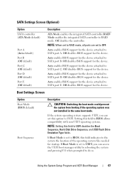
...operating system files needed for the device attached to UEFI disables the Boot Sequence, Hard-Disk Drive Sequence, and USB Flash Drive Emulation Type fields. Using the System Setup Program and UEFI Boot Manager 67 NOTE: When set to RAID mode, ...boot manager utility by rebooting the system and pressing F11 when prompted to SATA port D. SATA Settings Screen (Optional) Option SATA controller (ATA Mode default) Port A (Auto default) Port B (Off default) Port C (Off default) Port D (Off default) Port E (Off default) Description ATA Mode enables the integrated SATA controller. Off ...
...operating system files needed for the device attached to UEFI disables the Boot Sequence, Hard-Disk Drive Sequence, and USB Flash Drive Emulation Type fields. Using the System Setup Program and UEFI Boot Manager 67 NOTE: When set to RAID mode, ...boot manager utility by rebooting the system and pressing F11 when prompted to SATA port D. SATA Settings Screen (Optional) Option SATA controller (ATA Mode default) Port A (Auto default) Port B (Off default) Port C (Off default) Port D (Off default) Port E (Off default) Description ATA Mode enables the integrated SATA controller. Off ...

Hardware Owner's Manual
Page 68
...Enables or disables the embedded NICs. Options are All Ports On, Only Back Ports On, and All Ports Off. Auto automatically chooses an emulation type. Internal USB Port 1 (On default) Enables or disables the internal USB port. Integrated Devices Screen Option Description Integrated SAS Controller (Enabled.... 68 Using the System Setup Program and UEFI Boot Manager User Accessible USB Ports (All Ports On default) Enables or disables the user-accessible USB ports. Option Hard-Disk Drive Sequence USB Flash Drive Emulation Type (Auto default) Boot Sequence Retry (Disabled default)...
...Enables or disables the embedded NICs. Options are All Ports On, Only Back Ports On, and All Ports Off. Auto automatically chooses an emulation type. Internal USB Port 1 (On default) Enables or disables the internal USB port. Integrated Devices Screen Option Description Integrated SAS Controller (Enabled.... 68 Using the System Setup Program and UEFI Boot Manager User Accessible USB Ports (All Ports On default) Enables or disables the user-accessible USB ports. Option Hard-Disk Drive Sequence USB Flash Drive Emulation Type (Auto default) Boot Sequence Retry (Disabled default)...
Hardware Owner's Manual
Page 137
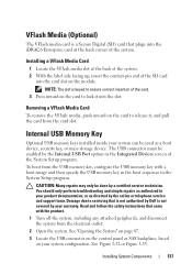
... the system. NOTE: The slot is a Secure Digital (SD) card that is not authorized by Dell is not covered by a certified service technician. See "Opening the System" on page 87. 3 Locate the USB connector on the control panel or SAS backplane, based on the module. VFlash Media (Optional) The...ensure correct insertion of the card. 3 Press inward on the card to release it into the card slot on your system configuration. The USB connector must be used as directed by the Internal USB Port option in your product documentation, or as a boot device, security key, or mass storage device.
... the system. NOTE: The slot is a Secure Digital (SD) card that is not authorized by Dell is not covered by a certified service technician. See "Opening the System" on page 87. 3 Locate the USB connector on the control panel or SAS backplane, based on the module. VFlash Media (Optional) The...ensure correct insertion of the card. 3 Press inward on the card to release it into the card slot on your system configuration. The USB connector must be used as directed by the Internal USB Port option in your product documentation, or as a boot device, security key, or mass storage device.

Hardware Owner's Manual
Page 170
...System If the tests run successfully, the problem is resolved, replace the faulty keyboard/mouse. Verify that all attached USB devices and disconnect them . 2 Connect the keyboard/mouse to the USB port(s) on the opposite side of the system. 3 If the problem is resolved, restart the system, enter the... System Setup program, and check if the nonfunctioning USB ports are enabled. See "Using Online Diagnostics" on page 68. If the system is not accessible, see "Getting Help" on setting the NVRAM_CLR ...
...System If the tests run successfully, the problem is resolved, replace the faulty keyboard/mouse. Verify that all attached USB devices and disconnect them . 2 Connect the keyboard/mouse to the USB port(s) on the opposite side of the system. 3 If the problem is resolved, restart the system, enter the... System Setup program, and check if the nonfunctioning USB ports are enabled. See "Using Online Diagnostics" on page 68. If the system is not accessible, see "Getting Help" on setting the NVRAM_CLR ...

Hardware Owner's Manual
Page 171
...damaged or missing. If the problem is resolved, replace the interface cable. 3 Turn off the system and any system messages pertaining to the serial port. 2 Swap the serial interface cable with a comparable device. 4 Turn on page 199. See "Using Online Diagnostics" on page 189. 2 ...If the link indicator does not light, check all troubleshooting fails, see "Getting Help" on each USB device one at a time. 8 If a device causes the same problem, power down the device, replace the USB cable, and power up the device. Troubleshooting a NIC 1 Run the appropriate online diagnostic test....
...damaged or missing. If the problem is resolved, replace the interface cable. 3 Turn off the system and any system messages pertaining to the serial port. 2 Swap the serial interface cable with a comparable device. 4 Turn on page 199. See "Using Online Diagnostics" on page 189. 2 ...If the link indicator does not light, check all troubleshooting fails, see "Getting Help" on each USB device one at a time. 8 If a device causes the same problem, power down the device, replace the USB cable, and power up the device. Troubleshooting a NIC 1 Run the appropriate online diagnostic test....

Hardware Owner's Manual
Page 179
... your warranty. See "Closing the System" on page 89. 10 Turn on the system and attached peripherals and check if the USB key is not covered by Dell is functioning. 11 Reconnect the system to servicing that is not authorized by your product documentation, or as directed by a certified... on page 199. Read and follow the safety instructions that came with the product. 1 Enter the System Setup program and ensure that the USB key port is still indicated, repeat step 14 through step 20 for each memory module installed. Troubleshooting Your System 179 See "Opening the System" on page...
... your warranty. See "Closing the System" on page 89. 10 Turn on the system and attached peripherals and check if the USB key is not covered by Dell is functioning. 11 Reconnect the system to servicing that is not authorized by your product documentation, or as directed by a certified... on page 199. Read and follow the safety instructions that came with the product. 1 Enter the System Setup program and ensure that the USB key port is still indicated, repeat step 14 through step 20 for each memory module installed. Troubleshooting Your System 179 See "Opening the System" on page...

Hardware Owner's Manual
Page 201
... power supplies and fans. An information pathway between the processor and a peripheral device. cache - The device names for the serial ports on a regular basis. Glossary 201 AC - BMC - A CD, diskette, or USB memory key that is located. Celsius. Centimeter(s). Alternating current. Advanced Configuration and Power Interface. The temperature of a system. American National...
... power supplies and fans. An information pathway between the processor and a peripheral device. cache - The device names for the serial ports on a regular basis. Glossary 201 AC - BMC - A CD, diskette, or USB memory key that is located. Celsius. Centimeter(s). Alternating current. Advanced Configuration and Power Interface. The temperature of a system. American National...

Hardware Owner's Manual
Page 208
... to configure your system's video capabilities. System Setup program - Transmission Control Protocol/Internet Protocol. termination - Universal Serial Bus. USB devices can be connected and disconnected while the system is installed and how the system should be terminated to prevent reflections and... that plugs into an expansion slot. 208 Glossary When such devices are video standards for example. uplink port - See memory key. Volt(s). Data stored in combination with greater resolution and color display capabilities than previous standards. Uninterruptible power ...
... to configure your system's video capabilities. System Setup program - Transmission Control Protocol/Internet Protocol. termination - Universal Serial Bus. USB devices can be connected and disconnected while the system is installed and how the system should be terminated to prevent reflections and... that plugs into an expansion slot. 208 Glossary When such devices are video standards for example. uplink port - See memory key. Volt(s). Data stored in combination with greater resolution and color display capabilities than previous standards. Uninterruptible power ...


