Getting Started Guide
Page 5
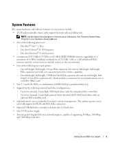
... two internal, 1-inch high, SATA hard drives with the integrated drive controllers. - See "Using the System Setup Program" in your system include: • 1U/1S rack-mountable chassis with an optional SAS controller card. • Optional remote access controller for PCI-X and PCIe RAC connectors. • Optional USB flash drive emulates...
... two internal, 1-inch high, SATA hard drives with the integrated drive controllers. - See "Using the System Setup Program" in your system include: • 1U/1S rack-mountable chassis with an optional SAS controller card. • Optional remote access controller for PCI-X and PCIe RAC connectors. • Optional USB flash drive emulates...
Getting Started Guide
Page 6
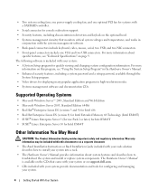
...may be included within this program, see "Technical Specifications" on page 9. The Hardware Owner's Manual is included with your system into a rack. • The Hardware Owner's Manual provides information about specific features, see "Using the System Setup Program" in the Hardware Owner's Manual... • Systems management circuitry that came with your system or on support.dell.com. • CDs included with your system provide documentation and tools for configuring and managing your rack solution describes how to troubleshoot the system and install or replace system components....
...may be included within this program, see "Technical Specifications" on page 9. The Hardware Owner's Manual is included with your system into a rack. • The Hardware Owner's Manual provides information about specific features, see "Using the System Setup Program" in the Hardware Owner's Manual... • Systems management circuitry that came with your system or on support.dell.com. • CDs included with your system provide documentation and tools for configuring and managing your rack solution describes how to troubleshoot the system and install or replace system components....

Getting Started Guide
Page 8
See your rack installation documentation for your system in a Rack Once you need them later. Keep all shipping materials in case you have read the "Safety Instructions" located in the rack installation documentation for instructions on installing your system, install the rails and the system in the rack. Installing the Rails and System in a rack. 6 Getting Started With Your System Unpacking the System Unpack your system and identify each item.
See your rack installation documentation for your system in a Rack Once you need them later. Keep all shipping materials in case you have read the "Safety Instructions" located in the rack installation documentation for instructions on installing your system, install the rails and the system in the rack. Installing the Rails and System in a rack. 6 Getting Started With Your System Unpacking the System Unpack your system and identify each item.

Hardware Owner's Manual (PDF)
Page 9
The system indicators and features are illustrated in this document or as a separate document. • The Rack Installation Guide and Rack Installation Instructions included with your rack solution describe how to install your system into a rack. • The Getting Started Guide provides an overview of system features, setting up your system, and technical specifications. •...
The system indicators and features are illustrated in this document or as a separate document. • The Rack Installation Guide and Rack Installation Instructions included with your rack solution describe how to install your system into a rack. • The Getting Started Guide provides an overview of system features, setting up your system, and technical specifications. •...

Hardware Owner's Manual (PDF)
Page 13
... status indicator lights up during normal system operation. The amber system status indicator flashes when the system needs attention due to locate a particular system within a rack. You can be pressed using certain operating systems. This button can use the systems management software to cause the indicators to flash to troubleshoot software...
... status indicator lights up during normal system operation. The amber system status indicator flashes when the system needs attention due to locate a particular system within a rack. You can be pressed using certain operating systems. This button can use the systems management software to cause the indicators to flash to troubleshoot software...

Hardware Owner's Manual (PDF)
Page 46
... on a work surface. 3 To remove the system cover, loosen the thumbscrew at the back of the rack to the locked position. If the system is installed on static rails, remove the system from the rack and place it on both sides. 5 Carefully lift the cover away from the system. Installing and Removing...
... on a work surface. 3 To remove the system cover, loosen the thumbscrew at the back of the rack to the locked position. If the system is installed on static rails, remove the system from the rack and place it on both sides. 5 Carefully lift the cover away from the system. Installing and Removing...

Hardware Owner's Manual (PDF)
Page 47
... thumbscrew at the back of the components inside the computer and protecting against electrostatic discharge. 1 Open the system. See Figure 3-3. 4 Replace the system in the rack, and reconnect the peripheral cables. 5 Reconnect the system to these components and the system memory.
... thumbscrew at the back of the components inside the computer and protecting against electrostatic discharge. 1 Open the system. See Figure 3-3. 4 Replace the system in the rack, and reconnect the peripheral cables. 5 Reconnect the system to these components and the system memory.

Hardware Owner's Manual (PDF)
Page 133
... a LAN (without a hard drive or bootable diskette). POST - processor - RAC - Random-access memory. Remote Access Service. Read-only memory. A ROM chip retains its operation in a rack. Revolutions per minute. Real-time clock. Each partition can divide a hard drive into multiple physical sections called partitions with the format command. PCI - PDU - Pixels...
... a LAN (without a hard drive or bootable diskette). POST - processor - RAC - Random-access memory. Remote Access Service. Read-only memory. A ROM chip retains its operation in a rack. Revolutions per minute. Real-time clock. Each partition can divide a hard drive into multiple physical sections called partitions with the format command. PCI - PDU - Pixels...

Rack Installation Guide
Page 5
... 5 Installation Instructions 6 Before You Begin 6 Important Safety Information 6 Rack Requirements for VersaRails 6 Four-Post Rack Installation 7 Rack Stabilizer Feet 7 Recommended Tools and Supplies 7 RapidRails Rack Kit Contents 8 VersaRails Rack Kit Contents 8 Installation Tasks 9 Removing the Rack Doors 10 Marking the Rack 10 Installing the Mounting Rails in the Rack 12 Installing and Removing Chassis Static Rail Modules 14...
... 5 Installation Instructions 6 Before You Begin 6 Important Safety Information 6 Rack Requirements for VersaRails 6 Four-Post Rack Installation 7 Rack Stabilizer Feet 7 Recommended Tools and Supplies 7 RapidRails Rack Kit Contents 8 VersaRails Rack Kit Contents 8 Installation Tasks 9 Removing the Rack Doors 10 Marking the Rack 10 Installing the Mounting Rails in the Rack 12 Installing and Removing Chassis Static Rail Modules 14...

Rack Installation Guide
Page 6
Figure 1-2. Figure 1-6. Figures Figure 1-1. Figure 1-15. Figure 1-5. Figure 1-9. Figure 1-12. Figure 1-13. Figure 1-4. Figure 1-7. Figure 1-11. Figure 1-10. RapidRails Rack Kit Contents 8 VersaRails Rack Kit Contents 9 One Rack Unit 10 Marking the Vertical Rails 11 Installing the RapidRails Mounting Rails 13 Installing the VersaRails Mounting Rails 14 Installing and Removing Static Rail Modules . . . . ...
Figure 1-2. Figure 1-6. Figures Figure 1-1. Figure 1-15. Figure 1-5. Figure 1-9. Figure 1-12. Figure 1-13. Figure 1-4. Figure 1-7. Figure 1-11. Figure 1-10. RapidRails Rack Kit Contents 8 VersaRails Rack Kit Contents 9 One Rack Unit 10 Marking the Vertical Rails 11 Installing the RapidRails Mounting Rails 13 Installing the VersaRails Mounting Rails 14 Installing and Removing Static Rail Modules . . . . ...

Rack Installation Guide
Page 7
...-certified as a free-standing unit and as to be installed in any other systems/components in connection with such combinations. • System rack kits are secured to the rack. Systems are considered to various peripherals or supporting hardware. Failure to install stabilizers accordingly before working on any safety agencies. Install front and...
...-certified as a free-standing unit and as to be installed in any other systems/components in connection with such combinations. • System rack kits are secured to the rack. Systems are considered to various peripherals or supporting hardware. Failure to install stabilizers accordingly before working on any safety agencies. Install front and...

Rack Installation Guide
Page 8
... instructions on their casters. This precaution becomes increasingly important when systems are important to prevent injury to yourself and to others. One rack kit is required for support and to prevent the cabinet from rolling. This guide includes procedures for the following subsections when installing your... damage to the system and personal injury to yourself and to install the next system. Retract the leveling feet when relocating the rack cabinet. Your system may result in all of the procedures for each system that meets the specifications of cabinet control may be involved...
... instructions on their casters. This precaution becomes increasingly important when systems are important to prevent injury to yourself and to others. One rack kit is required for support and to prevent the cabinet from rolling. This guide includes procedures for the following subsections when installing your... damage to the system and personal injury to yourself and to install the next system. Retract the leveling feet when relocating the rack cabinet. Your system may result in all of the procedures for each system that meets the specifications of cabinet control may be involved...

Rack Installation Guide
Page 9
... on installing and anchoring the stabilizer feet. The stabilizer feet help prevent the rack from tipping over , potentially resulting in the rack. See the documentation provided with the rack cabinet for use in marking the mounting holes to install stabilizers accordingly before installing... carefully. Therefore, always install the stabilizer(s) before installing systems in a four-post rack cabinet: • #2 Phillips screwdriver • Masking tape or a felt-tip pen, for instructions on racks joined to tip over . Recommended Tools and Supplies You may need the following items...
... on installing and anchoring the stabilizer feet. The stabilizer feet help prevent the rack from tipping over , potentially resulting in the rack. See the documentation provided with the rack cabinet for use in marking the mounting holes to install stabilizers accordingly before installing... carefully. Therefore, always install the stabilizer(s) before installing systems in a four-post rack cabinet: • #2 Phillips screwdriver • Masking tape or a felt-tip pen, for instructions on racks joined to tip over . Recommended Tools and Supplies You may need the following items...

Rack Installation Guide
Page 10
... Contents • One pair of threads per inch is identified as a 10-32 screw. 8 Rack Installation Guide RapidRails Rack Kit Contents • One pair of RapidRails mounting rails • Releasable tie wraps (2) (not shown in procedural steps are identified by size and number of ...
... Contents • One pair of threads per inch is identified as a 10-32 screw. 8 Rack Installation Guide RapidRails Rack Kit Contents • One pair of RapidRails mounting rails • Releasable tie wraps (2) (not shown in procedural steps are identified by size and number of ...

Rack Installation Guide
Page 11
... are provided for the RapidRails kit, the VersaRails kit, and the Static Rail kit. Rack Installation Guide 9 Figure 1-2. VersaRails Rack Kit Contents 10-32 x 0.5-inch flangehead Phillips screws (8) mounting rails (2) releasable tie wrap attachment points (2) Installation Tasks Installing a rack kit involves performing the following tasks (described in detail in subsequent sections) in their...
... are provided for the RapidRails kit, the VersaRails kit, and the Static Rail kit. Rack Installation Guide 9 Figure 1-2. VersaRails Rack Kit Contents 10-32 x 0.5-inch flangehead Phillips screws (8) mounting rails (2) releasable tie wrap attachment points (2) Installation Tasks Installing a rack kit involves performing the following tasks (described in detail in subsequent sections) in their...

Rack Installation Guide
Page 12
... and numbers in the documentation provided with center-to-center hole spacing (beginning at the top hole of a 1-U space) of the number marking on the rack. If you want, you can make a note of 15.9 mm, 15.9 mm, and 12.7 mm (0.625 inch, 0.625 inch, and 0.5 inch) for the front and... back vertical rails (see Figure 1-3). One Rack Unit 1 U (44 mm or 1.75 inches) 12.7 mm (0.5 inch) 15.9 mm (0.625 inch) 15.9 mm (0.625 inch) 12.7 mm (0.5 inch) CAUTION: If you must allow...
... and numbers in the documentation provided with center-to-center hole spacing (beginning at the top hole of a 1-U space) of the number marking on the rack. If you want, you can make a note of 15.9 mm, 15.9 mm, and 12.7 mm (0.625 inch, 0.625 inch, and 0.5 inch) for the front and... back vertical rails (see Figure 1-3). One Rack Unit 1 U (44 mm or 1.75 inches) 12.7 mm (0.5 inch) 15.9 mm (0.625 inch) 15.9 mm (0.625 inch) 12.7 mm (0.5 inch) CAUTION: If you must allow...

Rack Installation Guide
Page 13
... mark just above the original mark you made (or count up three holes in a rack that meets EIA-310 standards) and mark the rack's front vertical rails with a felttipped pen or masking tape (if you are installing in the rack. Figure 1-4. Marking the Vertical Rails tape on the vertical rails (see Figure 1-4). 2... hole). The bottom of each 1-U space is at the middle of the narrowest metal area between holes (marked with a horizontal line on the rack's front vertical rails where you want to locate the bottom of tape indicates where the system's upper edge will be located on vertical rail...
... mark just above the original mark you made (or count up three holes in a rack that meets EIA-310 standards) and mark the rack's front vertical rails with a felttipped pen or masking tape (if you are installing in the rack. Figure 1-4. Marking the Vertical Rails tape on the vertical rails (see Figure 1-4). 2... hole). The bottom of each 1-U space is at the middle of the narrowest metal area between holes (marked with a horizontal line on the rack's front vertical rails where you want to locate the bottom of tape indicates where the system's upper edge will be located on vertical rail...

Rack Installation Guide
Page 14
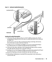
... the RapidRails Mounting Rails 1 At the front of the rack cabinet, position one of the rack. 12 Rack Installation Guide The top mounting hook on the front mounting-bracket flange should enter the top hole between the marks you made on the vertical ... mounting hooks seat and the push button pops out and clicks. 4 Repeat step 1 through step 3 for the mounting rail on the other side of the rack. 5 Ensure that the mounting rails are mounted at the same vertical position on both sides of the RapidRails mounting rails so that its mounting-bracket...
... the RapidRails Mounting Rails 1 At the front of the rack cabinet, position one of the rack. 12 Rack Installation Guide The top mounting hook on the front mounting-bracket flange should enter the top hole between the marks you made on the vertical ... mounting hooks seat and the push button pops out and clicks. 4 Repeat step 1 through step 3 for the mounting rail on the other side of the rack. 5 Ensure that the mounting rails are mounted at the same vertical position on both sides of the RapidRails mounting rails so that its mounting-bracket...
Rack Installation Guide
Page 15
...-holes to secure the mounting rail to the back vertical rail. 5 Repeat step 1 through step 4 for the mounting rail on the other side of the rack. 6 Ensure that its mounting-bracket flange fits between the marks you made on the back vertical rail. 4 Install two 10-32 x 0.5-inch flange-head... Phillips screws in the mounting-bracket flange's top- The three holes on the front of the rack. Figure 1-5. and bottom-holes to secure the mounting rail to the front vertical rail. 3 At the back of the VersaRails mounting rails so that the...
...-holes to secure the mounting rail to the back vertical rail. 5 Repeat step 1 through step 4 for the mounting rail on the other side of the rack. 6 Ensure that its mounting-bracket flange fits between the marks you made on the back vertical rail. 4 Install two 10-32 x 0.5-inch flange-head... Phillips screws in the mounting-bracket flange's top- The three holes on the front of the rack. Figure 1-5. and bottom-holes to secure the mounting rail to the front vertical rail. 3 At the back of the VersaRails mounting rails so that the...

Rack Installation Guide
Page 16
... of the chassis toward the front and midpoint (see Figure 1-7). 3 To seat the rails, pull up on the front latches attached to the front of rack rails modules (2) Installing and Removing Chassis Static Rail Modules NOTE: You do not need to remove the optional front bezel to install or remove the...
... of the chassis toward the front and midpoint (see Figure 1-7). 3 To seat the rails, pull up on the front latches attached to the front of rack rails modules (2) Installing and Removing Chassis Static Rail Modules NOTE: You do not need to remove the optional front bezel to install or remove the...


