Getting Started Guide
Page 5
...chassis with the integrated drive controllers. - System Features The major hardware and software features of your Hardware Owner's Manual. • One of the following processors: - One Intel Celeron® D, 300 Sequence - One Intel® Core™ 2 Duo - This option requires a riser card with a x4...DDR2 SDRAM memory, upgradable to two internal, 1-inch high, SATA hard drives with support for remote systems management. Up to view processor information. Getting Started With Your System 3 One full-height, half-length, 133MHz/64 bit PCI-X expansion slot and one full-height...
...chassis with the integrated drive controllers. - System Features The major hardware and software features of your Hardware Owner's Manual. • One of the following processors: - One Intel Celeron® D, 300 Sequence - One Intel® Core™ 2 Duo - This option requires a riser card with a x4...DDR2 SDRAM memory, upgradable to two internal, 1-inch high, SATA hard drives with support for remote systems management. Up to view processor information. Getting Started With Your System 3 One full-height, half-length, 133MHz/64 bit PCI-X expansion slot and one full-height...
Getting Started Guide
Page 11
... Two optional riser cards Riser 1 PCIe PCIe One Intel® Core™ 2 Duo processor or One Intel Celeron® D, 300 Sequence processor or One Intel Pentium® 4, 600 Sequence processor 533 MHz minimum 800 MHz minimum 1066 MHz minimum 256 KB at least 2 MB at ... ships with the system. Complete the 0perating System Setup If you purchased a preinstalled operating system, see the Quick Installation Guide. Technical Specifications Processor Processor type Front-side bus speed Intel Celeron D Intel Pentium 4 Intel Core 2 Duo Internal cache Intel Celeron D Intel Pentium 4 Intel Core...
... Two optional riser cards Riser 1 PCIe PCIe One Intel® Core™ 2 Duo processor or One Intel Celeron® D, 300 Sequence processor or One Intel Pentium® 4, 600 Sequence processor 533 MHz minimum 800 MHz minimum 1066 MHz minimum 256 KB at least 2 MB at ... ships with the system. Complete the 0perating System Setup If you purchased a preinstalled operating system, see the Quick Installation Guide. Technical Specifications Processor Processor type Front-side bus speed Intel Celeron D Intel Pentium 4 Intel Core 2 Duo Internal cache Intel Celeron D Intel Pentium 4 Intel Core...
Hardware Owner's Manual (PDF)
Page 5
... Riser Card 66 Installing the Riser Card 67 System Memory 67 Memory Module Installation Guidelines 68 Installing Memory Modules 69 Removing Memory Modules 70 Processor 70 Replacing the Processor 71 Control Panel Assembly (Service-Only Procedure 73 Removing the Control Panel Assembly 73 Installing the Control Panel Assembly 74 System Board (Service...
... Riser Card 66 Installing the Riser Card 67 System Memory 67 Memory Module Installation Guidelines 68 Installing Memory Modules 69 Removing Memory Modules 70 Processor 70 Replacing the Processor 71 Control Panel Assembly (Service-Only Procedure 73 Removing the Control Panel Assembly 73 Installing the Control Panel Assembly 74 System Board (Service...
Hardware Owner's Manual (PDF)
Page 21
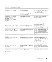
... board. Update the BIOS firmware. System Messages (continued) Message The amount of system memory has changed the memory configuration. No micro code update loaded for processor 0 Causes Corrective Actions Faulty memory module. Information only, if you have changed . Faulty battery; If the problem persists, see "Troubleshooting the System Battery" on page...
... board. Update the BIOS firmware. System Messages (continued) Message The amount of system memory has changed the memory configuration. No micro code update loaded for processor 0 Causes Corrective Actions Faulty memory module. Information only, if you have changed . Faulty battery; If the problem persists, see "Troubleshooting the System Battery" on page...
Hardware Owner's Manual (PDF)
Page 22
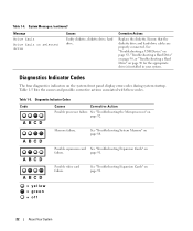
... System A B C D Memory failure. Table 1-5 lists the causes and possible corrective actions associated with these codes. Table 1-4. Table 1-5. Diagnostic Indicator Codes Code Causes Corrective Action Possible processor failure. See "Troubleshooting Expansion Cards" on page 90 for the appropriate drive(s) installed in your system. See "Troubleshooting the Microprocessor" on failure. A B C D A B C D A B C D Possible expansion card...
... System A B C D Memory failure. Table 1-5 lists the causes and possible corrective actions associated with these codes. Table 1-4. Table 1-5. Diagnostic Indicator Codes Code Causes Corrective Action Possible processor failure. See "Troubleshooting Expansion Cards" on page 90 for the appropriate drive(s) installed in your system. See "Troubleshooting the Microprocessor" on failure. A B C D A B C D A B C D Possible expansion card...

Hardware Owner's Manual (PDF)
Page 26
... continues a task. Time-of the Diagnostics Checklist in that accompanied the operating system or application. Super I/O chip failure; See "Getting Help" on page 92. faulty processor See "Troubleshooting the Microprocessor" on board page 103. Warning messages usually interrupt the task and require you to respond by either the application or the...
... continues a task. Time-of the Diagnostics Checklist in that accompanied the operating system or application. Super I/O chip failure; See "Getting Help" on page 92. faulty processor See "Troubleshooting the Microprocessor" on board page 103. Warning messages usually interrupt the task and require you to respond by either the application or the...
Hardware Owner's Manual (PDF)
Page 33
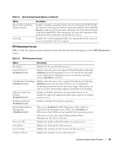
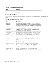
... Report Keyboard Errors (Report default) Asset Tag Description Enables or disables reporting of each processor. Table 2-3. Logical Processor (Enabled default) Displays when the processor supports Hyper-Threading technology. Demand-Based Power Management (Disabled default) When set to Disabled...during the POST. Core Speed Displays the clock speed of cores in the processor design. Virtualization Technology (Disabled default) Displays when the processor(s) support Virtualization Technology. Displays the customer-programmable asset tag number for the ...
... Report Keyboard Errors (Report default) Asset Tag Description Enables or disables reporting of each processor. Table 2-3. Logical Processor (Enabled default) Displays when the processor supports Hyper-Threading technology. Demand-Based Power Management (Disabled default) When set to Disabled...during the POST. Core Speed Displays the clock speed of cores in the processor design. Virtualization Technology (Disabled default) Displays when the processor(s) support Virtualization Technology. Displays the customer-programmable asset tag number for the ...
Hardware Owner's Manual (PDF)
Page 34
... boot from the network. Enables or disables the system's secondary integrated NIC. CPU Information Screen (continued) Option 64-Bit Technology Description Specifies if the installed processor supports Intel® 64-bit extensions. Table 2-3. Table 2-4. ATA Mode sets the SATA subsystem to the channel and the external IDE controller is not detected...
... boot from the network. Enables or disables the system's secondary integrated NIC. CPU Information Screen (continued) Option 64-Bit Technology Description Specifies if the installed processor supports Intel® 64-bit extensions. Table 2-3. Table 2-4. ATA Mode sets the SATA subsystem to the channel and the external IDE controller is not detected...
Hardware Owner's Manual (PDF)
Page 43
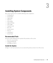
...; Optical drive • Hard drives • Fan assembly • Optional PCI fan • Power supply • Expansion cards • Riser card • System memory • Processor • Control panel • System board Recommended Tools You may need the following items to perform the procedures in this section: • Key to the...
...; Optical drive • Hard drives • Fan assembly • Optional PCI fan • Power supply • Expansion cards • Riser card • System memory • Processor • Control panel • System board Recommended Tools You may need the following items to perform the procedures in this section: • Key to the...
Hardware Owner's Manual (PDF)
Page 44
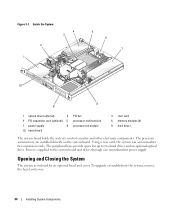
...Installing System Components The peripheral bays provide space for up to the system board and drives through one nonredundant power supply. The processor and memory are installed directly on the system board. Power is enclosed by an optional bezel and cover. Inside the System... 10 8 9 1 optical drive (optional) 2 4 PCI expansion card (optional) 5 7 power supply 8 10 hard drive 0 PCI fan processor and heat sink processor fan module 3 riser card 6 memory modules (4) 9 hard drive 1 The system board holds the system's control circuitry and other electronic components. Figure ...
...Installing System Components The peripheral bays provide space for up to the system board and drives through one nonredundant power supply. The processor and memory are installed directly on the system board. Power is enclosed by an optional bezel and cover. Inside the System... 10 8 9 1 optical drive (optional) 2 4 PCI expansion card (optional) 5 7 power supply 8 10 hard drive 0 PCI fan processor and heat sink processor fan module 3 riser card 6 memory modules (4) 9 hard drive 1 The system board holds the system's control circuitry and other electronic components. Figure ...

Hardware Owner's Manual (PDF)
Page 47
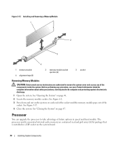
... shroud. Installing System Components 47 Before performing any of the system to these components and the system memory. Cooling Shroud The cooling shroud covers the processor and system battery and provides air flow to secure the cover. See "Opening the System" on the system. Closing the System 1 Ensure that you did...
... shroud. Installing System Components 47 Before performing any of the system to these components and the system memory. Cooling Shroud The cooling shroud covers the processor and system battery and provides air flow to secure the cover. See "Opening the System" on the system. Closing the System 1 Ensure that you did...

Hardware Owner's Manual (PDF)
Page 57
... proper cooling environment. See "Installing the PCI Fan Assembly" on page 46. 2 Remove the cooling shroud. See "Opening the System" on page 60 for the processor and memory modules. See Figure 3-11. 4 Remove the data cable from hard drive 1 if installed. See Figure 3-11. 5 Remove the hard drive 0 power cable if...
... proper cooling environment. See "Installing the PCI Fan Assembly" on page 46. 2 Remove the cooling shroud. See "Opening the System" on page 60 for the processor and memory modules. See Figure 3-11. 4 Remove the data cable from hard drive 1 if installed. See Figure 3-11. 5 Remove the hard drive 0 power cable if...
Hardware Owner's Manual (PDF)
Page 70
See "Opening the System" on page 47. Processor You can upgrade the processor to remove the system cover and access any procedure, see your Product Information Guide for complete information about safety precautions, working inside the system. See ... end of the socket until the memory module pops out of future options in a ZIF socket on the system board. 70 Installing System Components The processor and its associated internal cache memory are authorized to take advantage of the socket. See Figure 3-17. 4 Close the system. Installing and Removing a Memory Module...
See "Opening the System" on page 47. Processor You can upgrade the processor to remove the system cover and access any procedure, see your Product Information Guide for complete information about safety precautions, working inside the system. See ... end of the socket until the memory module pops out of future options in a ZIF socket on the system board. 70 Installing System Components The processor and its associated internal cache memory are authorized to take advantage of the socket. See Figure 3-17. 4 Close the system. Installing and Removing a Memory Module...

Hardware Owner's Manual (PDF)
Page 71
... Remove the cooling shroud. Installing System Components 71 NOTE: When you remove the heat sink, the possibility exists that you intend to remove the processor. Installing and Removing the Heat Sink 2 1 1 captive screws (4) 2 heat sink 4 Wait 30 seconds for complete information about safety precautions, ...to remove the system cover and access any procedure, see your Product Information Guide for the heat sink to loosen from the processor. Before performing any of the components inside the computer and protecting against electrostatic discharge. 1 Open the system. It is ...
... Remove the cooling shroud. Installing System Components 71 NOTE: When you remove the heat sink, the possibility exists that you intend to remove the processor. Installing and Removing the Heat Sink 2 1 1 captive screws (4) 2 heat sink 4 Wait 30 seconds for complete information about safety precautions, ...to remove the system cover and access any procedure, see your Product Information Guide for the heat sink to loosen from the processor. Before performing any of the components inside the computer and protecting against electrostatic discharge. 1 Open the system. It is ...

Hardware Owner's Manual (PDF)
Page 72
... the system. Do not pry the heat sink off of the processor. 6 Lift the heat sink off of the socket. See Figure 3-19. 8 Open the processor cover. Installing and Removing the Processor 4 5 3 2 1 1 processor socket release lever 4 processor cover 2 processor socket 5 pin-1 locators 3 processor 10 Unpack the new processor. 11 Ensure that the socket is in a clockwise, then counterclockwise...
... the system. Do not pry the heat sink off of the processor. 6 Lift the heat sink off of the socket. See Figure 3-19. 8 Open the processor cover. Installing and Removing the Processor 4 5 3 2 1 1 processor socket release lever 4 processor cover 2 processor socket 5 pin-1 locators 3 processor 10 Unpack the new processor. 11 Ensure that the socket is in a clockwise, then counterclockwise...

Hardware Owner's Manual (PDF)
Page 73
...the control panel cables. See "Opening the System" on page 47. Installing System Components 73 NOTE: Use the heat sink that the processor information matches the new system configuration. See "Using the System Setup Program" on page 29. 20 Run the system diagnostics to the...access any procedure, see your Product Information Guide for information about safety precautions, working inside the system. c Place the heat sink onto the processor. d Using a #2 Phillips screwdriver, tighten in a diagonal pattern the four captive screws that secure the heat sink to enter the System...
...the control panel cables. See "Opening the System" on page 47. Installing System Components 73 NOTE: Use the heat sink that the processor information matches the new system configuration. See "Using the System Setup Program" on page 29. 20 Run the system diagnostics to the...access any procedure, see your Product Information Guide for information about safety precautions, working inside the system. c Place the heat sink onto the processor. d Using a #2 Phillips screwdriver, tighten in a diagonal pattern the four captive screws that secure the heat sink to enter the System...

Hardware Owner's Manual (PDF)
Page 75
... cable from the FP_CONN1 connector on page 70. See Figure 6-2. 8 Remove all PCI expansion cards installed on page 47. 3 Remove the heat sink and processor. See Figure 6-2. 12 Pull up and out of the chassis. See Figure 3-21. 13 Using the tab on the system board tray, slide the system..."Opening the System" on page 71. 4 Remove the memory modules. b If the system hard drives are removed and replaced as a single assembly. See "Replacing the Processor" on page 46. 2 Remove the cooling shroud. See Figure 3-21. 14 Lay the system board tray down on the system board. NOTE: As you remove...
... cable from the FP_CONN1 connector on page 70. See Figure 6-2. 8 Remove all PCI expansion cards installed on page 47. 3 Remove the heat sink and processor. See Figure 6-2. 12 Pull up and out of the chassis. See Figure 3-21. 13 Using the tab on the system board tray, slide the system..."Opening the System" on page 71. 4 Remove the memory modules. b If the system hard drives are removed and replaced as a single assembly. See "Replacing the Processor" on page 46. 2 Remove the cooling shroud. See Figure 3-21. 14 Lay the system board tray down on the system board. NOTE: As you remove...

Hardware Owner's Manual (PDF)
Page 77
... cable to the IDE connector on the system board. 7 Install the riser card. See Figure 6-2 for the location of the SATA connectors. 11 Install the processor and heat sink. See Figure 6-2. 6 Connect the chassis intrusion cable to the controller card. See "Replacing the...
... cable to the IDE connector on the system board. 7 Install the riser card. See Figure 6-2 for the location of the SATA connectors. 11 Install the processor and heat sink. See Figure 6-2. 6 Connect the chassis intrusion cable to the controller card. See "Replacing the...
Hardware Owner's Manual (PDF)
Page 92
...and disconnect the system from the electrical outlet. If the tests fail, see "Getting Help" on page 46. 4 Ensure that the processor and heat sink are authorized to the electrical outlet, and turn on the system and attached peripherals. Troubleshooting the Microprocessor Problem • ... the System" on page 103. If the tests fail, see "Getting Help" on page 46. See "Using Dell PowerEdge Diagnostics" on page 71. 5 Close the system. See "Replacing the Processor" on page 93. 2 Turn off the system and attached peripherals, and disconnect the system from the electrical outlet....
...and disconnect the system from the electrical outlet. If the tests fail, see "Getting Help" on page 46. 4 Ensure that the processor and heat sink are authorized to the electrical outlet, and turn on the system and attached peripherals. Troubleshooting the Microprocessor Problem • ... the System" on page 103. If the tests fail, see "Getting Help" on page 46. See "Using Dell PowerEdge Diagnostics" on page 71. 5 Close the system. See "Replacing the Processor" on page 93. 2 Turn off the system and attached peripherals, and disconnect the system from the electrical outlet....
Hardware Owner's Manual (PDF)
Page 99
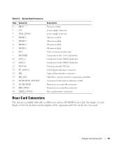
... 9 BATTERY 10 SATA_0 11 SATA_1 12 PCI FAN 13 FP_CONN1 14 IDE 15 HD_ACT 16 INTRUSION_SWITCH 17 I2C HEADER 18 BMC PROG 19 RISER_CONN1 Description Processor socket power supply connector power supply connector Memory module Memory module Memory module Memory module Power connector for the fans Connector for the 3.0 V coin battery...
... 9 BATTERY 10 SATA_0 11 SATA_1 12 PCI FAN 13 FP_CONN1 14 IDE 15 HD_ACT 16 INTRUSION_SWITCH 17 I2C HEADER 18 BMC PROG 19 RISER_CONN1 Description Processor socket power supply connector power supply connector Memory module Memory module Memory module Memory module Power connector for the fans Connector for the 3.0 V coin battery...


