
Service Manual
Page 2
... of Microsoft Corporation; Trademarks used in this document to refer to change without notice. © 1996-1997 Dell Computer Corporation. Other trademarks and trade names may be used in this text: Dell, the DELL logo, and OptiPlex are registered trademarks of 3Com Corporation. A01 Microsoft, Windows, and MS-DOS are registered trademarks of Intel...
... of Microsoft Corporation; Trademarks used in this document to refer to change without notice. © 1996-1997 Dell Computer Corporation. Other trademarks and trade names may be used in this text: Dell, the DELL logo, and OptiPlex are registered trademarks of 3Com Corporation. A01 Microsoft, Windows, and MS-DOS are registered trademarks of Intel...
Service Manual
Page 4
...-Supply Service Data 1-23 Pin Assignments for the DC Power Connectors 1-25 DC Power Distribution 1-26 OptiPlex NX Computer Power Supply 1-32 OptiPlex NX Pin Assignments for the DC Power Connectors . . . . 1-33 DC Power Distribution for the OptiPlex NX 1-34 Technical Specifications 1-36 Chapter 2 Basic Troubleshooting 2-1 Initial User Contact 2-1 External Visual Inspection 2-2 Observing...
...-Supply Service Data 1-23 Pin Assignments for the DC Power Connectors 1-25 DC Power Distribution 1-26 OptiPlex NX Computer Power Supply 1-32 OptiPlex NX Pin Assignments for the DC Power Connectors . . . . 1-33 DC Power Distribution for the OptiPlex NX 1-34 Technical Specifications 1-36 Chapter 2 Basic Troubleshooting 2-1 Initial User Contact 2-1 External Visual Inspection 2-2 Observing...

Service Manual
Page 5
Chapter 3 Beep Codes and Error Messages 3-1 POST Beep Codes 3-1 System Error Messages 3-3 Chapter 4 Removing and Replacing Parts on the Low-Profile Chassis 4-1 Recommended Tools 4-1 Precautionary Measures 4-2 Inside the Computer 4-3 Computer Cover 4-4 Eject, Power, and Reset Buttons 4-5 Front-Panel Inserts 4-6 Control Panel 4-7 Drives 4-8 3.5-Inch Diskette Drive Assembly 4-9 5.25-Inch Drive Assembly 4-10 Hard-Disk Drive Assembly 4-11 System Power Supply 4-12 Expansion Cards 4-13 Expansion-Card Cage 4-13 Expansion Card 4-14 Riser Board 4-15 System Board 4-16 System Board ...
Chapter 3 Beep Codes and Error Messages 3-1 POST Beep Codes 3-1 System Error Messages 3-3 Chapter 4 Removing and Replacing Parts on the Low-Profile Chassis 4-1 Recommended Tools 4-1 Precautionary Measures 4-2 Inside the Computer 4-3 Computer Cover 4-4 Eject, Power, and Reset Buttons 4-5 Front-Panel Inserts 4-6 Control Panel 4-7 Drives 4-8 3.5-Inch Diskette Drive Assembly 4-9 5.25-Inch Drive Assembly 4-10 Hard-Disk Drive Assembly 4-11 System Power Supply 4-12 Expansion Cards 4-13 Expansion-Card Cage 4-13 Expansion Card 4-14 Riser Board 4-15 System Board 4-16 System Board ...

Service Manual
Page 6
Floor Stand 5-4 Computer Cover 5-5 Eject, Power, and Reset Buttons 5-6 Front-Panel Inserts 5-7 Control Panel 5-8 Drives 5-9 Externally Accessible Drive Assemblies 5-10 3.5-Inch Diskette Drive Assembly 5-10 5.25-Inch Drive Assembly 5-11 Hard-Disk Drive Bracket 5-12 Hard-Disk Drive 5-13 System Power Supply 5-14 Expansion Cards 5-15 Expansion-Card Cage 5-15 Expansion Card 5-16 Riser Board 5-17 System Board 5-18 System Board Components 5-19 DIMMs 5-20 Video Memory 5-20 Microprocessor 5-22 SEC Cartridge/Heat Sink Assembly 5-22 System Battery 5-23 Chapter 6 Removing and ...
Floor Stand 5-4 Computer Cover 5-5 Eject, Power, and Reset Buttons 5-6 Front-Panel Inserts 5-7 Control Panel 5-8 Drives 5-9 Externally Accessible Drive Assemblies 5-10 3.5-Inch Diskette Drive Assembly 5-10 5.25-Inch Drive Assembly 5-11 Hard-Disk Drive Bracket 5-12 Hard-Disk Drive 5-13 System Power Supply 5-14 Expansion Cards 5-15 Expansion-Card Cage 5-15 Expansion Card 5-16 Riser Board 5-17 System Board 5-18 System Board Components 5-19 DIMMs 5-20 Video Memory 5-20 Microprocessor 5-22 SEC Cartridge/Heat Sink Assembly 5-22 System Battery 5-23 Chapter 6 Removing and ...

Service Manual
Page 7
Drives 6-10 Externally Accessible Drive Assemblies 6-10 3.5-Inch Diskette Drive Assembly 6-11 5.25-Inch Drive Assembly 6-13 Hard-Disk Drive Bracket 6-15 Hard-Disk Drive 6-16 System Power Supply 6-17 Expansion Cards 6-18 Expansion-Card Cage 6-18 Expansion Card 6-19 Riser Board 6-20 System Board 6-21 System Board Components 6-22 DIMMs 6-23 Video Memory 6-23 Microprocessor 6-25 SEC Cartridge/Heat Sink Assembly 6-25 System Battery 6-26 Chapter 7 Removing and Replacing Parts on the Net PC Chassis 7-1 Recommended Tools 7-1 Precautionary Measures 7-2 Stand for Vertical ...
Drives 6-10 Externally Accessible Drive Assemblies 6-10 3.5-Inch Diskette Drive Assembly 6-11 5.25-Inch Drive Assembly 6-13 Hard-Disk Drive Bracket 6-15 Hard-Disk Drive 6-16 System Power Supply 6-17 Expansion Cards 6-18 Expansion-Card Cage 6-18 Expansion Card 6-19 Riser Board 6-20 System Board 6-21 System Board Components 6-22 DIMMs 6-23 Video Memory 6-23 Microprocessor 6-25 SEC Cartridge/Heat Sink Assembly 6-25 System Battery 6-26 Chapter 7 Removing and Replacing Parts on the Net PC Chassis 7-1 Recommended Tools 7-1 Precautionary Measures 7-2 Stand for Vertical ...
Service Manual
Page 8
... Computer 1-13 Figure 1-10. System Board Jumpers 1-19 Figure 1-17. DC Power Connectors P2 (Low-Profile Chassis) and P7 (All OptiPlex GXa Chassis 1-26 Figure 1-21. DC Power Distribution for the Midsize and Mini Tower Computers 1-29 Figure 1-24. DC Power Cables for the...Midsize and Mini Tower Chassis); Chassis Configurations 1-2 Figure 1-2. Computer Orientation Information 1-22 Figure 1-18. P3, P4, P5, P6, and P9 (All OptiPlex GXa Chassis 1-25 Figure 1-20. Riser Board for the Midsize Computer 1-14 Figure 1-13. DC Power Cables for the Mini Tower Computer 1-15 Figure 1-...
... Computer 1-13 Figure 1-10. System Board Jumpers 1-19 Figure 1-17. DC Power Connectors P2 (Low-Profile Chassis) and P7 (All OptiPlex GXa Chassis 1-26 Figure 1-21. DC Power Distribution for the Midsize and Mini Tower Computers 1-29 Figure 1-24. DC Power Cables for the...Midsize and Mini Tower Chassis); Chassis Configurations 1-2 Figure 1-2. Computer Orientation Information 1-22 Figure 1-18. P3, P4, P5, P6, and P9 (All OptiPlex GXa Chassis 1-25 Figure 1-20. Riser Board for the Midsize Computer 1-14 Figure 1-13. DC Power Cables for the Mini Tower Computer 1-15 Figure 1-...
Service Manual
Page 9
... Figure 5-3. Front-Panel Insert Removal 5-7 Figure 5-6. Hard-Disk Drive Bracket Removal 5-12 Figure 5-12. DC Power Connector P3 for the OptiPlex NX Computer 1-34 Figure 1-30. Internal View of the Midsize Computer 5-3 Figure 5-2. Eject, Power, and Reset Button Removal 4-5 Figure 4-4.... Hard-Disk Drive Assembly Removal 4-11 Figure 4-10. SEC Cartridge/Heat Sink Removal 4-20 Figure 4-20. DC Power Cables for the OptiPlex NX 1-34 Figure 1-29. DIMM Installation 4-18 Figure 4-18. Control Panel Removal 5-8 Figure 5-7. Hard-Disk Drive Removal 5-13 xi Drive...
... Figure 5-3. Front-Panel Insert Removal 5-7 Figure 5-6. Hard-Disk Drive Bracket Removal 5-12 Figure 5-12. DC Power Connector P3 for the OptiPlex NX Computer 1-34 Figure 1-30. Internal View of the Midsize Computer 5-3 Figure 5-2. Eject, Power, and Reset Button Removal 4-5 Figure 4-4.... Hard-Disk Drive Assembly Removal 4-11 Figure 4-10. SEC Cartridge/Heat Sink Removal 4-20 Figure 4-20. DC Power Cables for the OptiPlex NX 1-34 Figure 1-29. DIMM Installation 4-18 Figure 4-18. Control Panel Removal 5-8 Figure 5-7. Hard-Disk Drive Removal 5-13 xi Drive...

Service Manual
Page 10
Figure 5-13. System Power-Supply Removal 5-14 Figure 5-14. Riser Board Removal 5-17 Figure 5-17. DIMM Installation 5-20 Figure 5-21. Hard-Disk Drive Removal 6-16 Figure 6-15. Expansion-Card Cage Removal 5-15 Figure 5-15. System Board Components 5-19 Figure 5-19. DIMM Removal 5-20 Figure 5-20. SEC Cartridge/Heat Sink Removal 5-22 Figure 5-23. Internal View of the Mini Tower Computer 6-3 Figure 6-2. Computer Cover Removal 6-4 Figure 6-3. Front-Bezel Removal 6-5 Figure 6-4. Expansion-Card Removal 6-19 Figure 6-18. Installing a Video-Memory Upgrade Module 6-24 ...
Figure 5-13. System Power-Supply Removal 5-14 Figure 5-14. Riser Board Removal 5-17 Figure 5-17. DIMM Installation 5-20 Figure 5-21. Hard-Disk Drive Removal 6-16 Figure 6-15. Expansion-Card Cage Removal 5-15 Figure 5-15. System Board Components 5-19 Figure 5-19. DIMM Removal 5-20 Figure 5-20. SEC Cartridge/Heat Sink Removal 5-22 Figure 5-23. Internal View of the Mini Tower Computer 6-3 Figure 6-2. Computer Cover Removal 6-4 Figure 6-3. Front-Bezel Removal 6-5 Figure 6-4. Expansion-Card Removal 6-19 Figure 6-18. Installing a Video-Memory Upgrade Module 6-24 ...

Service Manual
Page 11
... Removal 7-9 Figure 7-9. SEC Cartridge/Heat Sink Removal 7-14 Figure 7-15. Table 1-2. System-Board Jumper Descriptions 1-20 Interrupt Assignments 1-20 DREQ Line Assignments 1-21 OptiPlex GXa DC Voltage Ranges 1-24 OptiPlex NX DC Voltage Ranges 1-32 Technical Specifications 1-36 POST Beep Codes 3-2 System Error Messages 3-4 System Setup Categories A-3 xiii Figure 7-3. System Power-Supply Removal...
... Removal 7-9 Figure 7-9. SEC Cartridge/Heat Sink Removal 7-14 Figure 7-15. Table 1-2. System-Board Jumper Descriptions 1-20 Interrupt Assignments 1-20 DREQ Line Assignments 1-21 OptiPlex GXa DC Voltage Ranges 1-24 OptiPlex NX DC Voltage Ranges 1-32 Technical Specifications 1-36 POST Beep Codes 3-2 System Error Messages 3-4 System Setup Categories A-3 xiii Figure 7-3. System Power-Supply Removal...

Service Manual
Page 12
... avoid the problem. Warnings, Cautions, and Notes Throughout this manual and the online System User's Guide, Dell provides the Diagnostics and Troubleshooting Guide for troubleshooting procedures and instructions on using the Dell Diagnostics to service Dell computer systems is a basic knowledge of text printed in bold type or in IBMcompatible PC troubleshooting techniques...
... avoid the problem. Warnings, Cautions, and Notes Throughout this manual and the online System User's Guide, Dell provides the Diagnostics and Troubleshooting Guide for troubleshooting procedures and instructions on using the Dell Diagnostics to service Dell computer systems is a basic knowledge of text printed in bold type or in IBMcompatible PC troubleshooting techniques...

Service Manual
Page 13
...300-MHz), upgradable desktop computers built around high-performance Intel® Pentium® II microprocessors with MMXTM technology. The Dell OptiPlex GXa and OptiPlex NX systems are identified by the phrase "Enhanced Manageability," which is printed on the computer's FCC label and also...NIC controller or an enhanced manageability (EM) system board with optional NIC controller and support for the Dell® OptiPlex® GXa and Optiplex NX family of the OptiPlex GXa and OptiPlex NX families; Chapters 1 through 3 and Appendix A contain information that applies to all models of ...
...300-MHz), upgradable desktop computers built around high-performance Intel® Pentium® II microprocessors with MMXTM technology. The Dell OptiPlex GXa and OptiPlex NX systems are identified by the phrase "Enhanced Manageability," which is printed on the computer's FCC label and also...NIC controller or an enhanced manageability (EM) system board with optional NIC controller and support for the Dell® OptiPlex® GXa and Optiplex NX family of the OptiPlex GXa and OptiPlex NX families; Chapters 1 through 3 and Appendix A contain information that applies to all models of ...
Service Manual
Page 14
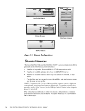
Chassis Configurations Chassis Differences The three OptiPlex GXa and the OptiPlex Net PC chassis configurations differ primarily in the four chassis configurations, a separate parts removal and replacement chapter (Chapters 4 through 7) is turned off. Due to the ... a power supply with a secondary winding that provides trickle ("flea") power for the Wakeup On LAN feature when computer power is provided for each chassis type. 1-2 Dell OptiPlex GXa and OptiPlex NX Systems Service Manual Low-Profile Chassis Midsize Chassis Mini Tower Chassis Net PC Chassis Figure 1-1.
Chassis Configurations Chassis Differences The three OptiPlex GXa and the OptiPlex Net PC chassis configurations differ primarily in the four chassis configurations, a separate parts removal and replacement chapter (Chapters 4 through 7) is turned off. Due to the ... a power supply with a secondary winding that provides trickle ("flea") power for the Wakeup On LAN feature when computer power is provided for each chassis type. 1-2 Dell OptiPlex GXa and OptiPlex NX Systems Service Manual Low-Profile Chassis Midsize Chassis Mini Tower Chassis Net PC Chassis Figure 1-1.

Service Manual
Page 15
... (see Chapters 1 through 3 and Appendix A). Pentium II Microprocessor All systems in the following similarities: • Use the same system board (OptiPlex GXa systems can use the EM system board) • Identical operational characteristics (same BIOS, POST, memory, microprocessor, external I/O ports, and so ...cache SRAM is installed (standard or enhanced manageability version). Standard Features The features described in the OptiPlex GXa and OptiPlex NX computer families incorporate the Pentium II microprocessor for information about Dell-supported microprocessor upgrades.
... (see Chapters 1 through 3 and Appendix A). Pentium II Microprocessor All systems in the following similarities: • Use the same system board (OptiPlex GXa systems can use the EM system board) • Identical operational characteristics (same BIOS, POST, memory, microprocessor, external I/O ports, and so ...cache SRAM is installed (standard or enhanced manageability version). Standard Features The features described in the OptiPlex GXa and OptiPlex NX computer families incorporate the Pentium II microprocessor for information about Dell-supported microprocessor upgrades.
Service Manual
Page 16
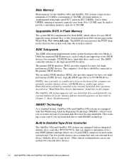
... positions described in "Hard-Disk Drive Service Information" found later in flash ROM, which can accommodate two external drive devices. 1-4 Dell OptiPlex GXa and OptiPlex NX Systems Service Manual The secondary EIDE interface (IDE2) also provides support for up to two EIDE devices (for example, CD-...up if your hard-disk drive has become unreliable. Main Memory Main memory for the OptiPlex GXa and OptiPlex NX systems ranges from Dell's home page on the World Wide Web (www.dell.com). The BIOS also incorporates the POST diagnostics that can accommodate only one external ...
... positions described in "Hard-Disk Drive Service Information" found later in flash ROM, which can accommodate two external drive devices. 1-4 Dell OptiPlex GXa and OptiPlex NX Systems Service Manual The secondary EIDE interface (IDE2) also provides support for up to two EIDE devices (for example, CD-...up if your hard-disk drive has become unreliable. Main Memory Main memory for the OptiPlex GXa and OptiPlex NX systems ranges from Dell's home page on the World Wide Web (www.dell.com). The BIOS also incorporates the POST diagnostics that can accommodate only one external ...

Service Manual
Page 17
... providing greater performance for devices attached to the PCI bus. Built-In Ethernet NIC Support (Optional on EM System Board) The OptiPlex GXa systems and Optiplex NX systems are both the 10BASE-T and 100BASE-T standards. Wakeup On LAN capability can be listed as described in the System...If the diskette drive and tape drive are available with a +5-VFP cable that connects to the ISA bus. Built-In SVGA Subsystem The OptiPlex GXa and OptiPlex NX systems include a built-in highperformance 64-bit accelerated graphics port (AGP) subsystem, implemented on the system board, only the diskette ...
... providing greater performance for devices attached to the PCI bus. Built-In Ethernet NIC Support (Optional on EM System Board) The OptiPlex GXa systems and Optiplex NX systems are both the 10BASE-T and 100BASE-T standards. Wakeup On LAN capability can be listed as described in the System...If the diskette drive and tape drive are available with a +5-VFP cable that connects to the ISA bus. Built-In SVGA Subsystem The OptiPlex GXa and OptiPlex NX systems include a built-in highperformance 64-bit accelerated graphics port (AGP) subsystem, implemented on the system board, only the diskette ...
Service Manual
Page 18
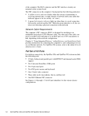
...network. Chapter 4, "Using Integrated Devices," in the Reference and Installation Guide provides instructions for the various chassis configurations. 1-6 Dell OptiPlex GXa and OptiPlex NX Systems Service Manual The RJ45 connector and the NIC interface circuitry are mounted on " state.) • A green ... to an RJ45 jack wall plate or to the online Network Administrator's Guide. of I/O Ports For desktop connectivity, the OptiPlex GXa and OptiPlex NX systems include the following indicators: • A yellow activity indicator flashes when the system is not detecting a physical connection...
...network. Chapter 4, "Using Integrated Devices," in the Reference and Installation Guide provides instructions for the various chassis configurations. 1-6 Dell OptiPlex GXa and OptiPlex NX Systems Service Manual The RJ45 connector and the NIC interface circuitry are mounted on " state.) • A green ... to an RJ45 jack wall plate or to the online Network Administrator's Guide. of I/O Ports For desktop connectivity, the OptiPlex GXa and OptiPlex NX systems include the following indicators: • A yellow activity indicator flashes when the system is not detecting a physical connection...
Service Manual
Page 19
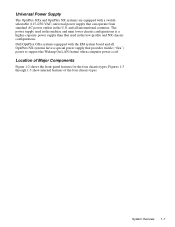
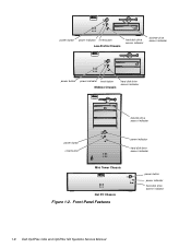
... four chassis types. Dell OptiPlex GXa systems equipped with a switchselectable (115-/230-VAC) universal power supply that can operate from standard AC power outlets in the U.S. Figures 1-3 through 1-5 show internal features of Major Components Figure 1-2 shows the front-panel features for the four chassis types; Universal Power Supply The OptiPlex GXa and OptiPlex NX systems are...
... four chassis types. Dell OptiPlex GXa systems equipped with a switchselectable (115-/230-VAC) universal power supply that can operate from standard AC power outlets in the U.S. Figures 1-3 through 1-5 show internal features of Major Components Figure 1-2 shows the front-panel features for the four chassis types; Universal Power Supply The OptiPlex GXa and OptiPlex NX systems are...
Service Manual
Page 20
Front-Panel Features power button power indicator hard-disk drive access indicator 1-8 Dell OptiPlex GXa and OptiPlex NX Systems Service Manual power button power indicator reset button Low-Profile Chassis hard-disk drive access indicator diskette-drive access indicator power button power indicator reset button Midsize Chassis hard-disk drive access indicator diskette-drive access indicator power button reset button power indicator hard-disk drive access indicator Mini Tower Chassis Net PC Chassis Figure 1-2.
Front-Panel Features power button power indicator hard-disk drive access indicator 1-8 Dell OptiPlex GXa and OptiPlex NX Systems Service Manual power button power indicator reset button Low-Profile Chassis hard-disk drive access indicator diskette-drive access indicator power button power indicator reset button Midsize Chassis hard-disk drive access indicator diskette-drive access indicator power button reset button power indicator hard-disk drive access indicator Mini Tower Chassis Net PC Chassis Figure 1-2.

Service Manual
Page 21
Internal View of the Low-Profile Chassis 3.5-inch diskette drive diskette/tape drive interface cable power supply security cable slot padlock ring AC power receptacle voltage selection switch parallel port connector serial port 1 connector mouse connector keyboard connector USB connectors (2) serial port 2 connector video connector NIC connector (optional) Figure 1-4. padlock ring voltage selection switch 3.5-inch diskette drive power supply AC power receptacle security cable slot diskette/tape drive interface cable hard-disk drive interface cable hard-disk drive parallel ...
Internal View of the Low-Profile Chassis 3.5-inch diskette drive diskette/tape drive interface cable power supply security cable slot padlock ring AC power receptacle voltage selection switch parallel port connector serial port 1 connector mouse connector keyboard connector USB connectors (2) serial port 2 connector video connector NIC connector (optional) Figure 1-4. padlock ring voltage selection switch 3.5-inch diskette drive power supply AC power receptacle security cable slot diskette/tape drive interface cable hard-disk drive interface cable hard-disk drive parallel ...

Service Manual
Page 23
... resolve conflicts. System Overview 1-11 Internal View of the Net PC Chassis expansion-card cage expansion-card slot AC power receptacle Advanced Expansion Features The OptiPlex GXa systems contain advanced expansion subsystems that can be accessed by the Device Manager, which can support a mixture of avoiding resource conflicts. power supply DC power...
... resolve conflicts. System Overview 1-11 Internal View of the Net PC Chassis expansion-card cage expansion-card slot AC power receptacle Advanced Expansion Features The OptiPlex GXa systems contain advanced expansion subsystems that can be accessed by the Device Manager, which can support a mixture of avoiding resource conflicts. power supply DC power...
