Service Manual
Page 1
... rights reserved. Removing and Replacing Parts Notes, Notices, and Cautions Throughout this text: Dell and OptiPlex are used in minor or moderate injury. Dell Computer Corporation disclaims any manner whatsoever without notice. © 2000 Dell Computer Corporation. Other trademarks and trade names may be used in this document to refer...italic type. Removing and Replacing Parts Midsize Chassis - NOTICE: A NOTICE indicates either the entities claiming the marks and names or their products. Dell™ OptiPlex™ GX200 Service Manual Small Form-Factor Chassis -
... rights reserved. Removing and Replacing Parts Notes, Notices, and Cautions Throughout this text: Dell and OptiPlex are used in minor or moderate injury. Dell Computer Corporation disclaims any manner whatsoever without notice. © 2000 Dell Computer Corporation. Other trademarks and trade names may be used in this document to refer...italic type. Removing and Replacing Parts Midsize Chassis - NOTICE: A NOTICE indicates either the entities claiming the marks and names or their products. Dell™ OptiPlex™ GX200 Service Manual Small Form-Factor Chassis -
Service Manual
Page 2
Back to avoid Removing and Replacing Parts: Dell™ OptiPlex™ GX200 Systems Service Manual Overview Recommended Tools Precautionary Measures Internal Views Computer Cover Eject, Power, and Reset Buttons Front-Panel Inserts Control... in the sequence listed: 1. Disconnect the computer and peripherals from electrostatic discharge (ESD). l You have performed the steps in the Dell OptiPlex low-profile chassis GX200 system. If you start to the system from their electrical outlets. Doing so reduces the potential for removing and replacing the components, assemblies...
Back to avoid Removing and Replacing Parts: Dell™ OptiPlex™ GX200 Systems Service Manual Overview Recommended Tools Precautionary Measures Internal Views Computer Cover Eject, Power, and Reset Buttons Front-Panel Inserts Control... in the sequence listed: 1. Disconnect the computer and peripherals from electrostatic discharge (ESD). l You have performed the steps in the Dell OptiPlex low-profile chassis GX200 system. If you start to the system from their electrical outlets. Doing so reduces the potential for removing and replacing the components, assemblies...
Service Manual
Page 3
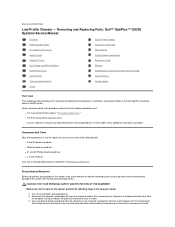
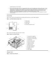
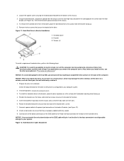
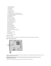
possible damage to discharge any static charge from your body before touching anything inside the computer. Verify that might harm internal components. Low-Profile Chassis Orientation View 1 System board 2 Hard-disk drive 3 Power supply 4 Externally accessible drive bays Figure 2 shows the low-profile chassis with the cover removed. Figure 1. If a wrist grounding strap is not available, touch any static electricity that the auxiliary power indicator on the riser board is on . If it is not on , you work inside the computer. Inside the Low-Profile Chassis 1 Diskette...
possible damage to discharge any static charge from your body before touching anything inside the computer. Verify that might harm internal components. Low-Profile Chassis Orientation View 1 System board 2 Hard-disk drive 3 Power supply 4 Externally accessible drive bays Figure 2 shows the low-profile chassis with the cover removed. Figure 1. If a wrist grounding strap is not available, touch any static electricity that the auxiliary power indicator on the riser board is on . If it is not on , you work inside the computer. Inside the Low-Profile Chassis 1 Diskette...
Service Manual
Page 4
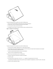
Lift the cover off the hooks at a slight angle (see Figure 3). 2. Reconnect all cables to complete the load operation, shut down toward the front of the chassis and insert the hooks on the cover into position. Disengage the tabs that the tabs catch the hooks inside the slots. 3. Align the bottom of the cover with the bottom of the computer. 3. Make sure that the securing buttons click into memory, allow the system to their connectors at the back of the chassis. 4. Enter System Setup. Figure 4. Computer Cover Replacement To replace the low-profile chassis computer cover,...
Lift the cover off the hooks at a slight angle (see Figure 3). 2. Reconnect all cables to complete the load operation, shut down toward the front of the chassis and insert the hooks on the cover into position. Disengage the tabs that the tabs catch the hooks inside the slots. 3. Align the bottom of the cover with the bottom of the computer. 3. Make sure that the securing buttons click into memory, allow the system to their connectors at the back of the chassis. 4. Enter System Setup. Figure 4. Computer Cover Replacement To replace the low-profile chassis computer cover,...
Service Manual
Page 5
... computer cover on the insert until it comes free. 3. Set Diskette Drive A and Diskette Drive B to verify that the system is operating correctly. Run the Dell Diagnostics to Not Installed.
... computer cover on the insert until it comes free. 3. Set Diskette Drive A and Diskette Drive B to verify that the system is operating correctly. Run the Dell Diagnostics to Not Installed.
Service Manual
Page 6
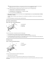
Slide the chassis intrusion switch out of its slot to remove it from the chassis (see "System Board Labels" for the location of the PANEL connector). 2. Hooks on the front of the control panel behind the mounting tab. Reset the chassis intrusion detector. When you remove it from the chassis. Disconnect the chassis intrusion switch cable connector from the PANEL connector on the system board (see Figure 8). 3. Disconnect the chassis intrusion switch cable connector from the chassis. Remove the control panel from the control panel. 4. Note the routing of the chassis ...
Slide the chassis intrusion switch out of its slot to remove it from the chassis (see "System Board Labels" for the location of the PANEL connector). 2. Hooks on the front of the control panel behind the mounting tab. Reset the chassis intrusion detector. When you remove it from the chassis. Disconnect the chassis intrusion switch cable connector from the PANEL connector on the system board (see Figure 8). 3. Disconnect the chassis intrusion switch cable connector from the chassis. Remove the control panel from the control panel. 4. Note the routing of the chassis ...
Service Manual
Page 7
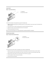
Drives NOTE: In all of the following procedures, left and right as you just removed. 5.25-inch Drive To remove the 5.25-inch drive/bracket assembly (the 5.25 drive is usually a CD-ROM drive), perform the following steps: 1. Hard-Disk Drive/Bracket Assembly Removal 1 Captive screw 2 Hinge tabs on back of the computer. Remove the diskette drive and bracket. 2. Lift the 5.25-inch drive/bracket straight up and out of the drive. 2. Pivot the 3.5-inch diskette drive upward 1 inch (2.5 cm), and then pull the drive away from the notched tabs on the left side of a 3.5-inch ...
Drives NOTE: In all of the following procedures, left and right as you just removed. 5.25-inch Drive To remove the 5.25-inch drive/bracket assembly (the 5.25 drive is usually a CD-ROM drive), perform the following steps: 1. Hard-Disk Drive/Bracket Assembly Removal 1 Captive screw 2 Hinge tabs on back of the computer. Remove the diskette drive and bracket. 2. Lift the 5.25-inch drive/bracket straight up and out of the drive. 2. Pivot the 3.5-inch diskette drive upward 1 inch (2.5 cm), and then pull the drive away from the notched tabs on the left side of a 3.5-inch ...
Service Manual
Page 8
Remove the four screws that they are properly cabled and firmly seated. 9. NOTICE: To avoid damaging the drive by ESD, ground yourself by touching an unpainted metal surface on the back of the drive (see Figure 12). 8. Connect a power cable to the power input connector on the back of electric shock, turn off the computer and any peripherals, disconnect them from the bracket, place the drive/bracket on a hard surface, which may damage the drive. Check all connectors to ensure that secure the bracket to the drive. 5. Grasp the drive/bracket, and pivot it . 1. Also, before...
Remove the four screws that they are properly cabled and firmly seated. 9. NOTICE: To avoid damaging the drive by ESD, ground yourself by touching an unpainted metal surface on the back of the drive (see Figure 12). 8. Connect a power cable to the power input connector on the back of electric shock, turn off the computer and any peripherals, disconnect them from the bracket, place the drive/bracket on a hard surface, which may damage the drive. Check all connectors to ensure that secure the bracket to the drive. 5. Grasp the drive/bracket, and pivot it . 1. Also, before...
Service Manual
Page 9
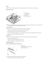
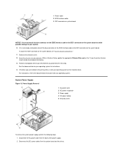
To locate the IDE1 connector on the hard-disk drive. If the drive you proceed to the documentation that came with your system. 10. Disconnect the AC power cable from the system board and the drives. Disconnect the DC power cables from the back of the power supply. 2. 1 Power cable 2 EIDE interface cable 3 IDE1 connector on system board NOTICE: You must attach the blue connector on the EIDE interface cable to the IDE1 connector on the system board. Replace the computer cover. 12. While in System Setup, update the appropriate Primary Drive option, 0 or 1 (see "System Board ...
To locate the IDE1 connector on the hard-disk drive. If the drive you proceed to the documentation that came with your system. 10. Disconnect the AC power cable from the system board and the drives. Disconnect the DC power cables from the back of the power supply. 2. 1 Power cable 2 EIDE interface cable 3 IDE1 connector on system board NOTICE: You must attach the blue connector on the EIDE interface cable to the IDE1 connector on the system board. Replace the computer cover. 12. While in System Setup, update the appropriate Primary Drive option, 0 or 1 (see "System Board ...
Service Manual
Page 10
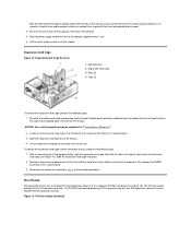
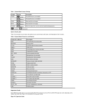
It is important to route these cables properly when you replace them to prevent them from the chassis. Examine any cables connected to where the cage must be placed upon removal from being pinched or crimped. 3. Reconnect any cables that the riser board is flush with the tabs in "Precautionary Measures." 2. Expansion-Card Cage Removal 1 Securing lever 2 Expansion-card cage 3 Slots (2) 4 Tabs (2) To remove the expansion-card cage, perform the following steps: 1. The PCI/ISA riser board provides one PCI expansion-card slot, one ISA expansion-card slot, and one ...
It is important to route these cables properly when you replace them to prevent them from the chassis. Examine any cables connected to where the cage must be placed upon removal from being pinched or crimped. 3. Reconnect any cables that the riser board is flush with the tabs in "Precautionary Measures." 2. Expansion-Card Cage Removal 1 Securing lever 2 Expansion-card cage 3 Slots (2) 4 Tabs (2) To remove the expansion-card cage, perform the following steps: 1. The PCI/ISA riser board provides one PCI expansion-card slot, one ISA expansion-card slot, and one ...
Service Manual
Page 11
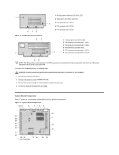
To remove the riser board, perform the following steps. System Board Components 1 Line-in the slots. 3. CAUTION: Ground yourself by touching an unpainted metal surface on the back of all its sockets and connectors. Remove the screws securing the riser board to the expansion-card cage. 4. Lift the riser board off the expansion-card cage. System Board Components Figure 17 shows the system board and the location of the computer. 1. only one of these two connectors can be used at any given time. Figure 17. PCI/ISA Riser Board (Optional) 1 Auxiliary power indicator LED (AUX_LED...
To remove the riser board, perform the following steps. System Board Components 1 Line-in the slots. 3. CAUTION: Ground yourself by touching an unpainted metal surface on the back of all its sockets and connectors. Remove the screws securing the riser board to the expansion-card cage. 4. Lift the riser board off the expansion-card cage. System Board Components Figure 17 shows the system board and the location of the computer. 1. only one of these two connectors can be used at any given time. Figure 17. PCI/ISA Riser Board (Optional) 1 Auxiliary power indicator LED (AUX_LED...
Service Manual
Page 12
Plastic plugs containing a wire fit down onto the pin(s) indicated. Otherwise, damage to your system is turned off its pin(s) and carefully fit it down over the pins. The wire connects the pins and creates a circuit. NOTICE: Make sure your system or unpredictable results may occur. Table 1 lists the system board jumpers and their settings. To change a jumper setting, pull the plug off before you change a jumper setting. System Board Jumpers Jumpers are small blocks on the system board. 2 Line-out connector 3 Microphone connector 4 NIC connector 5 Video connector 6 Serial ...
Plastic plugs containing a wire fit down onto the pin(s) indicated. Otherwise, damage to your system is turned off its pin(s) and carefully fit it down over the pins. The wire connects the pins and creates a circuit. NOTICE: Make sure your system or unpredictable results may occur. Table 1 lists the system board jumpers and their settings. To change a jumper setting, pull the plug off before you change a jumper setting. System Board Jumpers Jumpers are small blocks on the system board. 2 Line-out connector 3 Microphone connector 4 NIC connector 5 Video connector 6 Serial ...
Service Manual
Page 13
... PCI expansion-card connector Main power input connector 3.3-V power input connector Riser board connector Serial port connector Primary microprocessor connector USB connectors Expansion Cards Each GX200 low-profile chassis can accommodate 32-bit PCI expansion cards and 16-bit and 8-bit ISA expansion cards, depending on your system board, and it...
... PCI expansion-card connector Main power input connector 3.3-V power input connector Riser board connector Serial port connector Primary microprocessor connector USB connectors Expansion Cards Each GX200 low-profile chassis can accommodate 32-bit PCI expansion cards and 16-bit and 8-bit ISA expansion cards, depending on your system board, and it...
Service Manual
Page 14
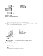
Remove the computer cover. 2. Remove the screw on configuring the card, making internal connections, or otherwise customizing it out of the card you want to unplug your computer from its connector. 5. To install an expansion card, perform the following steps: 1. Save the screw to the card. 3. 1 8-bit ISA expansion card 2 16-bit ISA expansion card 3 32-bit PCI expansion card Expansion-Card Removal To remove an expansion card, perform the following steps: 1. Expansion-Card Installation Figure 20. See the documentation that covers the card-slot opening . Filler Bracket ...
Remove the computer cover. 2. Remove the screw on configuring the card, making internal connections, or otherwise customizing it out of the card you want to unplug your computer from its connector. 5. To install an expansion card, perform the following steps: 1. Save the screw to the card. 3. 1 8-bit ISA expansion card 2 16-bit ISA expansion card 3 32-bit PCI expansion card Expansion-Card Removal To remove an expansion card, perform the following steps: 1. Expansion-Card Installation Figure 20. See the documentation that covers the card-slot opening . Filler Bracket ...
Service Manual
Page 15
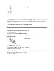
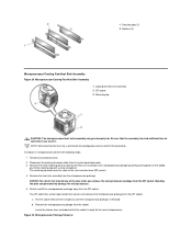
Insert the expansion card into its connector. Connect any cables that should be attached to access the RIMMs. 3. Locate the plastic securing clips at each end of the chassis as you insert the card into the expansion-card connector. If the expansion card is firmly seated in the connector, secure the card's mounting bracket to the chassis with the screw you to the card. Replace the computer cover and reset the chassis intrusion detector. Memory To remove a Rambus in step 2. 5. Remove the computer cover. 2. Press the clips outward until the RIMM disengages and pops out ...
Insert the expansion card into its connector. Connect any cables that should be attached to access the RIMMs. 3. Locate the plastic securing clips at each end of the chassis as you insert the card into the expansion-card connector. If the expansion card is firmly seated in the connector, secure the card's mounting bracket to the chassis with the screw you to the card. Replace the computer cover and reset the chassis intrusion detector. Memory To remove a Rambus in step 2. 5. Remove the computer cover. 2. Press the clips outward until the RIMM disengages and pops out ...
Service Manual
Page 16
... you touch it. The retaining clip hooks over the sides of the zero insertion force (ZIF) socket. 4. b. Microprocessor Package Removal Remove the computer cover. 2. NOTE: Dell recommends that secures and releases the microprocessor package from the ZIF socket. The ZIF socket has a lever-type handle that only a technically knowledgeable person perform...
... you touch it. The retaining clip hooks over the sides of the zero insertion force (ZIF) socket. 4. b. Microprocessor Package Removal Remove the computer cover. 2. NOTE: Dell recommends that secures and releases the microprocessor package from the ZIF socket. The ZIF socket has a lever-type handle that only a technically knowledgeable person perform...
Service Manual
Page 17
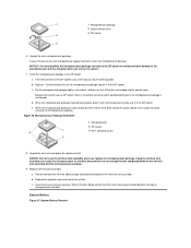
NOTICE: You must position the microprocessor package correctly in the replacement kit. If the release lever on the ZIF socket is fully seated, pivot the release lever back toward the system board until it snaps into the correct holes. When the microprocessor package is not all the pins are headed into place, securing the microprocessor package. Microprocessor Package Installation 1 Microprocessor 2 ZIF socket 3 Pin-1 (beveled corner) 8. Unpack the heat sink included in the ZIF socket to avoid permanent damage to the microprocessor and the computer when you replace the ...
NOTICE: You must position the microprocessor package correctly in the replacement kit. If the release lever on the ZIF socket is fully seated, pivot the release lever back toward the system board until it snaps into the correct holes. When the microprocessor package is not all the pins are headed into place, securing the microprocessor package. Microprocessor Package Installation 1 Microprocessor 2 ZIF socket 3 Pin-1 (beveled corner) 8. Unpack the heat sink included in the ZIF socket to avoid permanent damage to the microprocessor and the computer when you replace the ...
Service Manual
Page 18
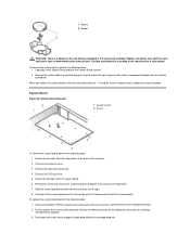
System Board Figure 28. Disconnect all cables from their connectors at the back of the chassis (see Figure 28). 7. When you are installing a microprocessor upgrade. 3. Disconnect all cables from the system board. 6. Set the jumpers on the new system board so that secures the system board to lift evenly and not twist the system board). 1 Battery 2 Socket CAUTION: There is incorrectly installed. Replace the battery only with the "+" facing up. To remove the system battery, perform the following steps: 1. Remove the system battery by the manufacturer. Remove the...
System Board Figure 28. Disconnect all cables from their connectors at the back of the chassis (see Figure 28). 7. When you are installing a microprocessor upgrade. 3. Disconnect all cables from the system board. 6. Set the jumpers on the new system board so that secures the system board to lift evenly and not twist the system board). 1 Battery 2 Socket CAUTION: There is incorrectly installed. Replace the battery only with the "+" facing up. To remove the system battery, perform the following steps: 1. Remove the system battery by the manufacturer. Remove the...

Service Manual
Page 19
Replace the expansion-card cage. 8. Replace the computer cover. 9. Reconnect all cables to Contents Page Back to the system board. 6. Push evenly on both sides of microprocessor installed. 4. Replace the 5.25-inch drive. 7. While in System Setup, confirm that the system data area correctly identifies the type of the system board as you slide and lock it into position (do not twist the system board). 5. Reset the chassis intrusion detector.
Replace the expansion-card cage. 8. Replace the computer cover. 9. Reconnect all cables to Contents Page Back to the system board. 6. Push evenly on both sides of microprocessor installed. 4. Replace the 5.25-inch drive. 7. While in System Setup, confirm that the system data area correctly identifies the type of the system board as you slide and lock it into position (do not twist the system board). 5. Reset the chassis intrusion detector.
Service Manual
Page 20
...outlet before touching anything inside the computer. You can replace or reinstall a part by performing the removal procedure in the Dell OptiPlex 200 midsize chassis system. Doing so reduces the potential for removing and replacing the components, assemblies, and subassemblies in ... the peripheral or removing the component to avoid possible damage to go out (see Removing and Replacing Parts: Dell™ OptiPlex™ GX200 System Service Manual Overview System Power Supply Recommended Tools System Board Components Precautionary Measures Expansion Cards Computer Cover Riser ...
...outlet before touching anything inside the computer. You can replace or reinstall a part by performing the removal procedure in the Dell OptiPlex 200 midsize chassis system. Doing so reduces the potential for removing and replacing the components, assemblies, and subassemblies in ... the peripheral or removing the component to avoid possible damage to go out (see Removing and Replacing Parts: Dell™ OptiPlex™ GX200 System Service Manual Overview System Power Supply Recommended Tools System Board Components Precautionary Measures Expansion Cards Computer Cover Riser ...
