
Statement of Volatility
Page 1
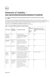
... will be between 1 GB to prevent loss of Non-Volatile Components on board diags), PXE diags. The Dell Latitude™ E6230/E6330/E6430/E6430ATG/E6530 contains both modules will be populated. present Stores memory manufacturer data and timing information for basic boot operation, PSA (on System Board Reference Description Volatility Description Designator User Accessible for...
... will be between 1 GB to prevent loss of Non-Volatile Components on board diags), PXE diags. The Dell Latitude™ E6230/E6330/E6430/E6430ATG/E6530 contains both modules will be populated. present Stores memory manufacturer data and timing information for basic boot operation, PSA (on System Board Reference Description Volatility Description Designator User Accessible for...

Owners Manual
Page 3
... ExpressCard...12 Installing the ExpressCard...12 Removing the Battery...12 Installing the Battery...13 Removing the Subscriber Identity Module (SIM) Card 13 Installing the Subscriber Identity Module (SIM) Card 13 Removing the Base Cover...13 Installing the Base Cover...14 Removing the Keyboard Trim...14... Hard Drive...17 Installing the Hard Drive...19 Removing the Optical Drive...19 Installing the Optical Drive...21 Removing the Memory...21 Installing the Memory...22 Removing the Processor...22 Installing the Processor...23 Removing the Wireless Local Area Network (WLAN) Card 23 Installing ...
... ExpressCard...12 Installing the ExpressCard...12 Removing the Battery...12 Installing the Battery...13 Removing the Subscriber Identity Module (SIM) Card 13 Installing the Subscriber Identity Module (SIM) Card 13 Removing the Base Cover...13 Installing the Base Cover...14 Removing the Keyboard Trim...14... Hard Drive...17 Installing the Hard Drive...19 Removing the Optical Drive...19 Installing the Optical Drive...21 Removing the Memory...21 Installing the Memory...22 Removing the Processor...22 Installing the Processor...23 Removing the Wireless Local Area Network (WLAN) Card 23 Installing ...

Owners Manual
Page 21
... eject latch to secure the optical drive latch. 6. Tighten the screw to secure the optical drive. 8. Install the battery. 9. 9. Removing the Memory 1. Remove the optical-drive door from the memory module until it pops up. 21 Secure the optical-drive door to the optical drive assembly. 4. Tighten the screws to secure the optical...
... eject latch to secure the optical drive latch. 6. Tighten the screw to secure the optical drive. 8. Install the battery. 9. 9. Removing the Memory 1. Remove the optical-drive door from the memory module until it pops up. 21 Secure the optical-drive door to the optical drive assembly. 4. Tighten the screws to secure the optical...

Owners Manual
Page 22
... processor cam lock in After Working Inside Your Computer. Removing the Processor 1. Remove: a) battery b) base cover c) heat sink 3. Press the securing clips to secure the memory module to remove the second memory module. Follow the procedures in Before Working Inside Your Computer. 2. Installing the Memory 1. 4. Remove the memory module from its connector on the system board. 5.
... processor cam lock in After Working Inside Your Computer. Removing the Processor 1. Remove: a) battery b) base cover c) heat sink 3. Press the securing clips to secure the memory module to remove the second memory module. Follow the procedures in Before Working Inside Your Computer. 2. Installing the Memory 1. 4. Remove the memory module from its connector on the system board. 5.

Owners Manual
Page 77
... LED Power LED Wireless LED Fault Description Blinking Solid Solid A possible processor failure has occurred. Solid Blinking Solid The memory modules are usually located either on when the computer reads or writes data. The device status LEDs are detected but has ... during initialization. They are installed/detected. The following table lists how to the system. Solid Blinking Blinking No memory modules are used to initialize or memory is in Option ROM initialization. Table 14. Blinking Blinking Solid A possible graphics card/video failure has occurred. ...
... LED Power LED Wireless LED Fault Description Blinking Solid Solid A possible processor failure has occurred. Solid Blinking Solid The memory modules are usually located either on when the computer reads or writes data. The device status LEDs are detected but has ... during initialization. They are installed/detected. The following table lists how to the system. Solid Blinking Blinking No memory modules are used to initialize or memory is in Option ROM initialization. Table 14. Blinking Blinking Solid A possible graphics card/video failure has occurred. ...
Owners Manual
Page 81
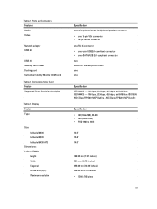
... Latitude E6530 Latitude E6430 ATG Dimensions: Latitude E6430: Height Width Diagonal Active area (X/Y) Maximum resolution Specification one microphone/stereo headphone/speakers connector • one 15-pin VGA connector • 19-pin HDMI connector one RJ-45 connector • one 4-pin USB 2.0-compliant connector • one eSATA/USB 2.0-compliant connector two one 8-in-1 memory... 309.40 mm x 173.95 mm • 1366 x 768 pixels 81 Table 21. Ports and Connectors Features Audio Video Network adapter USB 2.0 USB 3.0 Memory card reader Docking port Subscriber Identity Module (SIM) card Table 22.
... Latitude E6530 Latitude E6430 ATG Dimensions: Latitude E6430: Height Width Diagonal Active area (X/Y) Maximum resolution Specification one microphone/stereo headphone/speakers connector • one 15-pin VGA connector • 19-pin HDMI connector one RJ-45 connector • one 4-pin USB 2.0-compliant connector • one eSATA/USB 2.0-compliant connector two one 8-in-1 memory... 309.40 mm x 173.95 mm • 1366 x 768 pixels 81 Table 21. Ports and Connectors Features Audio Video Network adapter USB 2.0 USB 3.0 Memory card reader Docking port Subscriber Identity Module (SIM) card Table 22.


