User Manual
Page 1
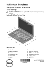
microphone 2. display release latch 3. display latch 6. Dell Latitude E6420/E6520 Setup and Features Information About Warnings WARNING: A WARNING indicates a potential for property damage, personal injury, or death. display 7. wireless switch 12. power button 8. USB 2.0 connectors (2) 10. optical drive Regulatory Model: P15G, P14F Regulatory Type: P15G001, P14F001 February 2011 Front View 1. camera status light 5. Latitude E6420 Front And Back View Figure 1. eSata/USB connector 9. volume control buttons 11. camera 4.
microphone 2. display release latch 3. display latch 6. Dell Latitude E6420/E6520 Setup and Features Information About Warnings WARNING: A WARNING indicates a potential for property damage, personal injury, or death. display 7. wireless switch 12. power button 8. USB 2.0 connectors (2) 10. optical drive Regulatory Model: P15G, P14F Regulatory Type: P15G001, P14F001 February 2011 Front View 1. camera status light 5. Latitude E6420 Front And Back View Figure 1. eSata/USB connector 9. volume control buttons 11. camera 4.
User Manual
Page 2
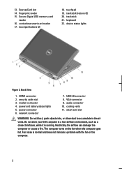
... 17. audio connector 10. Secure Digital (SD) memory-card reader 16. touchpad 19. device status lights Figure 2. HDMI connector 2. USB 2.0 connector 8. keyboard 22. power and battery status lights 5. Do not store your Dell computer in the air vents. fingerprint reader 15. VGA connector 9. cooling vents 11. ExpressCard slot 14. smart card slot...
... 17. audio connector 10. Secure Digital (SD) memory-card reader 16. touchpad 19. device status lights Figure 2. HDMI connector 2. USB 2.0 connector 8. keyboard 22. power and battery status lights 5. Do not store your Dell computer in the air vents. fingerprint reader 15. VGA connector 9. cooling vents 11. ExpressCard slot 14. smart card slot...
User Manual
Page 3
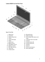
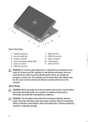
.... trackstick buttons (3) 21. trackstick 22. device status lights 3 display 7. optical drive 13. contactless smart card reader 18. Front View 1. eSata/USB connector 10. touchpad 19. camera 5. touchpad buttons (2) 20. Latitude E6520 Front And Back View Figure 3. display release latch 4. USB 2.0 connector 11. keyboard 23. power button 8. display latch 2. fingerprint reader 16. camera status light 6.
.... trackstick buttons (3) 21. trackstick 22. device status lights 3 display 7. optical drive 13. contactless smart card reader 18. Front View 1. eSata/USB connector 10. touchpad 19. camera 5. touchpad buttons (2) 20. Latitude E6520 Front And Back View Figure 3. display release latch 4. USB 2.0 connector 11. keyboard 23. power button 8. display latch 2. fingerprint reader 16. camera status light 6.
User Manual
Page 4
... electrical outlet may cause fire or equipment damage. 4 For additional best practices information, see www.dell.com/regulatory_compliance. Figure 4. network connector 2. USB 2.0 connector 9. USB 2.0 connector 7. The computer turns on the fan when the computer gets hot. WARNING: The AC... adapter works with your Dell computer in a low-airflow environment, such as a closed briefcase, while it is...
... electrical outlet may cause fire or equipment damage. 4 For additional best practices information, see www.dell.com/regulatory_compliance. Figure 4. network connector 2. USB 2.0 connector 9. USB 2.0 connector 7. The computer turns on the fan when the computer gets hot. WARNING: The AC... adapter works with your Dell computer in a low-airflow environment, such as a closed briefcase, while it is...
User Manual
Page 5
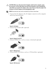
... the connector, not the cable itself, and pull firmly but gently to avoid damaging the cable. Connect the network cable (optional). Connect USB devices, such as a 1394 hard drive (optional). USB Connector 4. When you wrap the AC adapter cable, ensure that you did not order them. 1. AC Adapter 2. Figure 7. Figure 8. 1394 Connector...
... the connector, not the cable itself, and pull firmly but gently to avoid damaging the cable. Connect the network cable (optional). Connect USB devices, such as a 1394 hard drive (optional). USB Connector 4. When you wrap the AC adapter cable, ensure that you did not order them. 1. AC Adapter 2. Figure 7. Figure 8. 1394 Connector...


