User Manual
Page 2
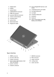
... 2.0 connector 8. power connector 6. wireless switch 13. touchpad buttons (2) 19. network connector 7. device status lights (hard disk, battery, and wireless) Figure 2. contactless smart card reader 18. keyboard 23. display latch 6. optical drive 14. smart card slot 2 display 7. VGA connector 9. powered USB 3.0 connector 11. HDMI connector 2. USB 3.0 connector 10. device status lights (power...
... 2.0 connector 8. power connector 6. wireless switch 13. touchpad buttons (2) 19. network connector 7. device status lights (hard disk, battery, and wireless) Figure 2. contactless smart card reader 18. keyboard 23. display latch 6. optical drive 14. smart card slot 2 display 7. VGA connector 9. powered USB 3.0 connector 11. HDMI connector 2. USB 3.0 connector 10. device status lights (power...
User Manual
Page 4
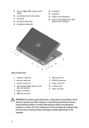
keyboard 22. device status lights (power, hard disk, and battery) 5. smart card slot WARNING: Do not block, push objects into, or allow dust to accumulate in a ... 8. audio connector 10. modem connector 4. power connector 6. USB 2.0 connector 7. Back View 1. Fan noise is running. security cable slot 3. cooling vents 11. Do not store your Dell computer in the air vents. 15. touchpad 18. volume control buttons 23. Secure Digital (SD) memory-card reader 16. device status lights (hard disk, battery...
keyboard 22. device status lights (power, hard disk, and battery) 5. smart card slot WARNING: Do not block, push objects into, or allow dust to accumulate in a ... 8. audio connector 10. modem connector 4. power connector 6. USB 2.0 connector 7. Back View 1. Fan noise is running. security cable slot 3. cooling vents 11. Do not store your Dell computer in the air vents. 15. touchpad 18. volume control buttons 23. Secure Digital (SD) memory-card reader 16. device status lights (hard disk, battery...
User Manual
Page 5
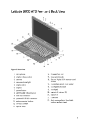
... (SD) memory-card reader 17. touchpad buttons (2) 19. trackstick buttons (3) 21. Front view 1. microphone 2. fingerprint reader 16. trackstick 22. USB 3.0 connector 10. Latitude E6430 ATG Front and Back View Figure 5. display latch 6. power button 8. volume control buttons 12. touchpad 20. keyboard 23. camera 4. eSATA/USB 2.0 connector 9. wireless switch 13. contactless smart card reader 18.
... (SD) memory-card reader 17. touchpad buttons (2) 19. trackstick buttons (3) 21. Front view 1. microphone 2. fingerprint reader 16. trackstick 22. USB 3.0 connector 10. Latitude E6430 ATG Front and Back View Figure 5. display latch 6. power button 8. volume control buttons 12. touchpad 20. keyboard 23. camera 4. eSATA/USB 2.0 connector 9. wireless switch 13. contactless smart card reader 18.
User Manual
Page 8
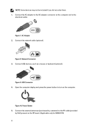
.... Connect the external antennae (purchased by Dell) present on the computer. Connect the network cable (optional). Network Connector 3. Open the computer display and press the power button to turn on the RF board. (Applicable only for E6430 ATG) 8 AC Adapter 2. Figure 7. Connect USB devices, such as a mouse or keyboard (optional). Figure 9. Power Button 5. NOTE...
.... Connect the external antennae (purchased by Dell) present on the computer. Connect the network cable (optional). Network Connector 3. Open the computer display and press the power button to turn on the RF board. (Applicable only for E6430 ATG) 8 AC Adapter 2. Figure 7. Connect USB devices, such as a mouse or keyboard (optional). Figure 9. Power Button 5. NOTE...
Owner's Manual
Page 3
... After Working Inside Your Computer...8 2 Removing and Installing Components 11 Recommended Tools...11 Removing the ATG Handle...11 Installing the ATG Handle...11 Removing the ATG Port Covers...12 Installing the ATG Port Covers...12 Removing the Secure Digital (SD) Card...12 Installing the Secure Digital (SD... (SIM) Card 14 Removing the Base Cover...15 Installing the Base Cover...15 Removing the Keyboard Trim...15 Installing the Keyboard Trim...16 Removing the Keyboard...16 Installing the Keyboard...18 Removing the Hard Drive...19 Installing the Hard Drive...20 Removing the Optical Drive...20 ...
... After Working Inside Your Computer...8 2 Removing and Installing Components 11 Recommended Tools...11 Removing the ATG Handle...11 Installing the ATG Handle...11 Removing the ATG Port Covers...12 Installing the ATG Port Covers...12 Removing the Secure Digital (SD) Card...12 Installing the Secure Digital (SD... (SIM) Card 14 Removing the Base Cover...15 Installing the Base Cover...15 Removing the Keyboard Trim...15 Installing the Keyboard Trim...16 Removing the Keyboard...16 Installing the Keyboard...18 Removing the Hard Drive...19 Installing the Hard Drive...20 Removing the Optical Drive...20 ...
Owner's Manual
Page 15
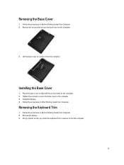
... After Working Inside Your Computer. Place the base cover to release it from the computer. 15 Install the battery. 4. Using a plastic scribe, pry under the keyboard trim to align with the screw holes on the computer. 2. Lift the base cover to the computer. 3. Installing the Base Cover 1. Tighten the screws to...
... After Working Inside Your Computer. Place the base cover to release it from the computer. 15 Install the battery. 4. Using a plastic scribe, pry under the keyboard trim to align with the screw holes on the computer. 2. Lift the base cover to the computer. 3. Installing the Base Cover 1. Tighten the screws to...

Owner's Manual
Page 16
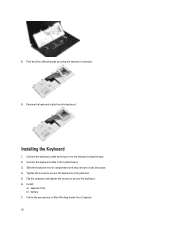
Installing the Keyboard Trim 1. Install the battery. 4. Remove the screws that secure the keyboard to remove the keyboard trim from the unit. Remove: a) battery b) keyboard trim 3. Removing the Keyboard 1. Lift up to computer. 16 Press along the sides and bottom. 5. 4. Follow the procedures in After Working Inside Your Computer. Pry the keyboard trim along the sides of the keyboard trim until it clicks in place. 3. Follow the procedures in Before Working Inside Your Computer. 2. Align the keyboard trim to its slot. 2.
Installing the Keyboard Trim 1. Install the battery. 4. Remove the screws that secure the keyboard to remove the keyboard trim from the unit. Remove: a) battery b) keyboard trim 3. Removing the Keyboard 1. Lift up to computer. 16 Press along the sides and bottom. 5. 4. Follow the procedures in After Working Inside Your Computer. Pry the keyboard trim along the sides of the keyboard trim until it clicks in place. 3. Follow the procedures in Before Working Inside Your Computer. 2. Align the keyboard trim to its slot. 2.

Owner's Manual
Page 17
Remove the screws that secure the keyboard to access the keyboard cable. 6. Remove the keyboard from the system board. 7. Disconnect the keyboard cable from the computer. 17 4. Lift and turn the keyboard to the palmrest assembly. 5.
Remove the screws that secure the keyboard to access the keyboard cable. 6. Remove the keyboard from the system board. 7. Disconnect the keyboard cable from the computer. 17 4. Lift and turn the keyboard to the palmrest assembly. 5.
Owner's Manual
Page 18
...and ensure that it to secure the keyboard. 6. Flip the computer and tighten the screws to the keyboard using the tape. 2. Slide the keyboard into place. 4. Follow the procedures in After Working Inside Your Computer. 18 8. Installing the Keyboard 1. Tighten the screws to the system ...board. 3. Connect the keyboard cable to secure the keyboard on the palmrest. 5....
...and ensure that it to secure the keyboard. 6. Flip the computer and tighten the screws to the keyboard using the tape. 2. Slide the keyboard into place. 4. Follow the procedures in After Working Inside Your Computer. 18 8. Installing the Keyboard 1. Tighten the screws to the system ...board. 3. Connect the keyboard cable to secure the keyboard on the palmrest. 5....
Owner's Manual
Page 29
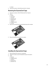
Remove: a) battery b) base cover c) hard drive d) bluetooth card e) keyboard trim f) keyboard g) display assembly h) palmrest 3. Remove the screws that secure the ExpressCard cage to the computer. 3. Follow the procedures in After Working Inside Your Computer. Place the ... Cage 1. Follow the procedures in Before Working Inside Your Computer. 2. Tighten the screws to secure the ExpressCard cage to the computer. 4. Install: a) palmrest b) display assembly c) keyboard d) keyboard trim e) bluetooth card 29 b) battery 4.
Remove: a) battery b) base cover c) hard drive d) bluetooth card e) keyboard trim f) keyboard g) display assembly h) palmrest 3. Remove the screws that secure the ExpressCard cage to the computer. 3. Follow the procedures in After Working Inside Your Computer. Place the ... Cage 1. Follow the procedures in Before Working Inside Your Computer. 2. Tighten the screws to secure the ExpressCard cage to the computer. 4. Install: a) palmrest b) display assembly c) keyboard d) keyboard trim e) bluetooth card 29 b) battery 4.
Owner's Manual
Page 30
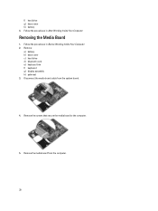
Follow the procedures in Before Working Inside Your Computer. 2. Follow the procedures in After Working Inside Your Computer. Remove the screws that secure the media board to the computer. 5. Remove: a) battery b) base cover c) hard drive d) bluetooth card e) keyboard trim f) keyboard g) display assembly h) palmrest 3. f) hard drive g) base cover h) battery 4. Disconnect the media board cable from the computer. 30 Remove the media board from the system board. 4. Removing the Media Board 1.
Follow the procedures in Before Working Inside Your Computer. 2. Follow the procedures in After Working Inside Your Computer. Remove the screws that secure the media board to the computer. 5. Remove: a) battery b) base cover c) hard drive d) bluetooth card e) keyboard trim f) keyboard g) display assembly h) palmrest 3. f) hard drive g) base cover h) battery 4. Disconnect the media board cable from the computer. 30 Remove the media board from the system board. 4. Removing the Media Board 1.
Owner's Manual
Page 31
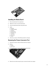
... in Before Working Inside Your Computer. 2. Follow the procedures in its compartment. 2. Disconnect the power-connector cable from the system board. 4. Install: a) palmrest b) display assembly c) keyboard d) keyboard trim e) bluetooth card f) hard drive g) base cover h) battery 5. Removing the Power-Connector Port 1. Follow the procedures in After Working Inside Your Computer. Remove: a) battery b) base...
... in Before Working Inside Your Computer. 2. Follow the procedures in its compartment. 2. Disconnect the power-connector cable from the system board. 4. Install: a) palmrest b) display assembly c) keyboard d) keyboard trim e) bluetooth card f) hard drive g) base cover h) battery 5. Removing the Power-Connector Port 1. Follow the procedures in After Working Inside Your Computer. Remove: a) battery b) base...
Owner's Manual
Page 33
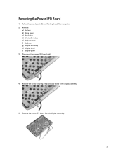
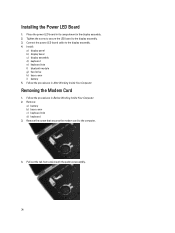
Removing the Power LED Board 1. Remove the power LED board from the display assembly. 33 Follow the procedures in Before Working Inside Your Computer. 2. Remove: a) battery b) base cover c) hard drive d) bluetooth module e) keyboard trim f) keyboard g) display assembly h) display bezel i) display panel 3. Disconnect the power LED board cable. 4. Remove the screw securing the power LED board to the display assembly. 5.
Removing the Power LED Board 1. Remove the power LED board from the display assembly. 33 Follow the procedures in Before Working Inside Your Computer. 2. Remove: a) battery b) base cover c) hard drive d) bluetooth module e) keyboard trim f) keyboard g) display assembly h) display bezel i) display panel 3. Disconnect the power LED board cable. 4. Remove the screw securing the power LED board to the display assembly. 5.
Owner's Manual
Page 34
Tighten the screw to secure the LED board to the display assembly. 4. Install: a) display panel b) display bezel c) display assembly d) keyboard e) keyboard trim f) bluetooth module g) hard drive h) base cover i) battery 5. Remove: a) battery b) base cover c) keyboard trim d) keyboard 3. Connect the power LED board cable to the display assembly. 3. Removing the Modem Card 1. Remove the screw that secures...
Tighten the screw to secure the LED board to the display assembly. 4. Install: a) display panel b) display bezel c) display assembly d) keyboard e) keyboard trim f) bluetooth module g) hard drive h) base cover i) battery 5. Remove: a) battery b) base cover c) keyboard trim d) keyboard 3. Connect the power LED board cable to the display assembly. 3. Removing the Modem Card 1. Remove the screw that secures...
Owner's Manual
Page 35
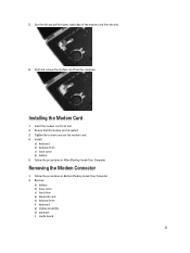
... and pull the lower right edge of the modem card from the computer. Installing the Modem Card 1. Remove: a) battery b) base cover c) hard drive d) bluetooth card e) keyboard trim f) keyboard g) display assembly h) palmrest i) media board 35 Install: a) keyboard b) keyboard trim c) base cover d) battery 5. 5.
... and pull the lower right edge of the modem card from the computer. Installing the Modem Card 1. Remove: a) battery b) base cover c) hard drive d) bluetooth card e) keyboard trim f) keyboard g) display assembly h) palmrest i) media board 35 Install: a) keyboard b) keyboard trim c) base cover d) battery 5. 5.
Owner's Manual
Page 37
... to secure the modem connector bracket. 4. Follow the procedures in After Working Inside Your Computer. Remove: a) battery b) base cover c) hard drive d) optical drive e) bluetooth card f) keyboard trim g) keyboard h) display assembly i) palmrest j) media board k) ExpressCard cage l) system board 37 Installing the Modem Connector 1. Install: a) system board b) ExpressCard cage c) media board d) palmrest e) display assembly...
... to secure the modem connector bracket. 4. Follow the procedures in After Working Inside Your Computer. Remove: a) battery b) base cover c) hard drive d) optical drive e) bluetooth card f) keyboard trim g) keyboard h) display assembly i) palmrest j) media board k) ExpressCard cage l) system board 37 Installing the Modem Connector 1. Install: a) system board b) ExpressCard cage c) media board d) palmrest e) display assembly...
Owner's Manual
Page 38
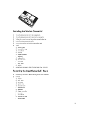
Remove the I /O board. 3. Remove: a) battery b) base cover 38 Tighten the screws to the computer. 4. Install: a) system board b) ExpressCard cage c) media board d) palmrest e) display assembly f) keyboard g) keyboard trim h) bluetooth card i) hard drive j) optical drive k) base cover l) battery 4. Removing the Hard-Drive Support Plate 1. Remove the screw that secures the I /O board in its ...
Remove the I /O board. 3. Remove: a) battery b) base cover 38 Tighten the screws to the computer. 4. Install: a) system board b) ExpressCard cage c) media board d) palmrest e) display assembly f) keyboard g) keyboard trim h) bluetooth card i) hard drive j) optical drive k) base cover l) battery 4. Removing the Hard-Drive Support Plate 1. Remove the screw that secures the I /O board in its ...
Owner's Manual
Page 39
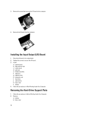
Lift the hard-drive support plate from the computer. Place the hard-drive support plate in its compartment. 2. c) hard drive d) bluetooth card e) keyboard trim f) keyboard g) display assembly h) palmrest i) media board j) ExpressCard cage k) system board 3. Tighten the screws to secure the hard-drive support plate to the computer.... plate to the computer. 3. Installing the Hard-Drive Support Plate 1. Install: a) system board b) ExpressCard cage c) media board d) palmrest e) display assembly f) keyboard g) keyboard trim h) hard drive i) bluetooth card j) base cover k) battery 39
Lift the hard-drive support plate from the computer. Place the hard-drive support plate in its compartment. 2. c) hard drive d) bluetooth card e) keyboard trim f) keyboard g) display assembly h) palmrest i) media board j) ExpressCard cage k) system board 3. Tighten the screws to secure the hard-drive support plate to the computer.... plate to the computer. 3. Installing the Hard-Drive Support Plate 1. Install: a) system board b) ExpressCard cage c) media board d) palmrest e) display assembly f) keyboard g) keyboard trim h) hard drive i) bluetooth card j) base cover k) battery 39
Owner's Manual
Page 40
Remove the screws that secure the palmrest assembly to the base of the computer. 4. Disconnect the LED cable from the system board. 40 Disconnect the touchpad cable from the system board. 6. Follow the procedures in Before Working Inside Your Computer. 2. Remove: a) battery b) base cover c) hard drive d) bluetooth card e) keyboard trim f) keyboard 3. Flip the computer over and remove the screws that secure the palmrest assembly to the computer. 5. Follow the procedures in After Working Inside Your Computer. 4. Removing the Palmrest 1.
Remove the screws that secure the palmrest assembly to the base of the computer. 4. Disconnect the LED cable from the system board. 40 Disconnect the touchpad cable from the system board. 6. Follow the procedures in Before Working Inside Your Computer. 2. Remove: a) battery b) base cover c) hard drive d) bluetooth card e) keyboard trim f) keyboard 3. Flip the computer over and remove the screws that secure the palmrest assembly to the computer. 5. Follow the procedures in After Working Inside Your Computer. 4. Removing the Palmrest 1.
Owner's Manual
Page 41
Connect the following cables: a) SD card b) touchpad c) LED 3. Install: a) keyboard b) keyboard trim c) bluetooth module d) hard drive e) base cover f) battery 41 Installing the Palmrest 1. 7. Lift and remove the palmrest from the system board. 8. Tighten the screws to secure the palmrest to its original position in the computer and snap it into place. 2. Align the palmrest assembly to the computer. 4. Disconnect the SD card cable from the computer.
Connect the following cables: a) SD card b) touchpad c) LED 3. Install: a) keyboard b) keyboard trim c) bluetooth module d) hard drive e) base cover f) battery 41 Installing the Palmrest 1. 7. Lift and remove the palmrest from the system board. 8. Tighten the screws to secure the palmrest to its original position in the computer and snap it into place. 2. Align the palmrest assembly to the computer. 4. Disconnect the SD card cable from the computer.


