Service Manual
Page 8
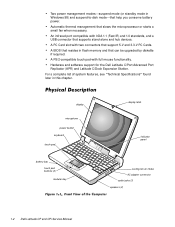
... buttons (2) modular bay display latch indicator panel cooling-fan air intake AC adapter connector audio jacks (3) speakers (2) 1-2 Dell Latitude CP and CPi Service Manual An infrared port compatible with two connectors that can be upgraded by diskette if required. For a complete list of system...stand-alone and hub devices. Automatic thermal management that help you conserve battery power. Hardware and software support for the Dell Latitude C/Port Advanced Port Replicator (APR) and Latitude C/Dock Expansion Station. A PC Card slot with IrDA 1.1 (Fast IR) and 1.0 standards, and a USB...
... buttons (2) modular bay display latch indicator panel cooling-fan air intake AC adapter connector audio jacks (3) speakers (2) 1-2 Dell Latitude CP and CPi Service Manual An infrared port compatible with two connectors that can be upgraded by diskette if required. For a complete list of system...stand-alone and hub devices. Automatic thermal management that help you conserve battery power. Hardware and software support for the Dell Latitude C/Port Advanced Port Replicator (APR) and Latitude C/Dock Expansion Station. A PC Card slot with IrDA 1.1 (Fast IR) and 1.0 standards, and a USB...
Service Manual
Page 10
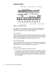
... a maintenance (trickle) charge to or from the hard-disk drive, or to keep the battery at full capacity. 1-4 Dell Latitude CP and CPi Service Manual The following conditions: The indicator turns green while the AC adapter is receiving stable power. If the power indicator is off,...in the modular bay. power indicator drive activity indicator battery indicator numbers lock indicator capitals lock indicator scroll lock indicator The Latitude CP or CPi computer has three indicators on the display assembly's indicator panel and three on without blinking. During the normal charging...
... a maintenance (trickle) charge to or from the hard-disk drive, or to keep the battery at full capacity. 1-4 Dell Latitude CP and CPi Service Manual The following conditions: The indicator turns green while the AC adapter is receiving stable power. If the power indicator is off,...in the modular bay. power indicator drive activity indicator battery indicator numbers lock indicator capitals lock indicator scroll lock indicator The Latitude CP or CPi computer has three indicators on the display assembly's indicator panel and three on without blinking. During the normal charging...
Service Manual
Page 12
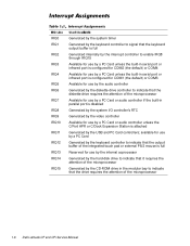
... Card controllers; available for use by a PC Card Generated by the keyboard controller to indicate that the diskette drive requires the attention of the microprocessor 1-6 Dell Latitude CP and CPi Service Manual
... Card controllers; available for use by a PC Card Generated by the keyboard controller to indicate that the diskette drive requires the attention of the microprocessor 1-6 Dell Latitude CP and CPi Service Manual
Service Manual
Page 14
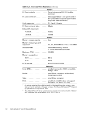
.... The Microsoft Windows NT ® 4.0 operating system does not support zoom video. 2 The Latitude CP and CPi do not support memory modules from previous models of Dell portable computers, such as the Latitude XP, XPi, XPi CD, and LM. 1-8 Dell Latitude CP and CPi Service Manual unidirectional, bidirectional, or ECP Video one 15-hole connector PS/2 one 6-hole mini...
.... The Microsoft Windows NT ® 4.0 operating system does not support zoom video. 2 The Latitude CP and CPi do not support memory modules from previous models of Dell portable computers, such as the Latitude XP, XPi, XPi CD, and LM. 1-8 Dell Latitude CP and CPi Service Manual unidirectional, bidirectional, or ECP Video one 15-hole connector PS/2 one 6-hole mini...
Service Manual
Page 16
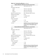
...pitch 0.31 mm Power consumption: Panel (typical 0.7 W Backlight 1.6 or 2.4 W Controls brightness can be controlled with key combinations, the Display window in the Dell Control Center, or the System Setup program Type active-matrix color (TFT) Dimensions (active area): Height 202.8 mm (7.98 inches) Width 270.3 mm (10...Dot pitch 0.26 mm Power consumption: Panel (typical 1.7 W Backlight 2.6 W Controls brightness can be controlled with key combinations, the Display window in the Dell Control Center, or the System Setup program 1-10 Dell Latitude CP and CPi Service Manual
...pitch 0.31 mm Power consumption: Panel (typical 0.7 W Backlight 1.6 or 2.4 W Controls brightness can be controlled with key combinations, the Display window in the Dell Control Center, or the System Setup program Type active-matrix color (TFT) Dimensions (active area): Height 202.8 mm (7.98 inches) Width 270.3 mm (10...Dot pitch 0.26 mm Power consumption: Panel (typical 1.7 W Backlight 2.6 W Controls brightness can be controlled with key combinations, the Display window in the Dell Control Center, or the System Setup program 1-10 Dell Latitude CP and CPi Service Manual
Service Manual
Page 18
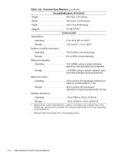
...;F) 3 Battery performance features such as charge time and life span can vary according to the conditions under which the computer and battery are used. 1-12 Dell Latitude CP and CPi Service Manual
...;F) 3 Battery performance features such as charge time and life span can vary according to the conditions under which the computer and battery are used. 1-12 Dell Latitude CP and CPi Service Manual
Service Manual
Page 20
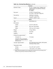
... weigh more or less, depending on its configuration. 7 Measured with a hard-disk drive, a battery in the battery bay, a diskette drive in head-parked position. 1-14 Dell Latitude CP and CPi Service Manual
... weigh more or less, depending on its configuration. 7 Measured with a hard-disk drive, a battery in the battery bay, a diskette drive in head-parked position. 1-14 Dell Latitude CP and CPi Service Manual
Service Manual
Page 22
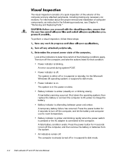
... listed for 4 seconds to charge the battery. A low-battery warning occurred. To perform a visual inspection, follow these steps: Look at the indicators to -disk mode. 2-2 Dell Latitude CP and CPi Service Manual Press the power button for that condition: Power indicator is on or blinking slowly). A temporary battery failure has occurred.
... listed for 4 seconds to charge the battery. A low-battery warning occurred. To perform a visual inspection, follow these steps: Look at the indicators to -disk mode. 2-2 Dell Latitude CP and CPi Service Manual Press the power button for that condition: Power indicator is on or blinking slowly). A temporary battery failure has occurred.
Service Manual
Page 24
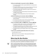
... connector on the computer's I /O panel. Yes. The mouse's ball and push buttons operate freely. Proceed to a power source and free of the Dell Latitude CP Reference and Troubleshooting Guide. 2-4 Dell Latitude CP and CPi Service Manual The captive screws that secure the connectors at each end of the interface cable are free of obvious physical damage. No further...
... connector on the computer's I /O panel. Yes. The mouse's ball and push buttons operate freely. Proceed to a power source and free of the Dell Latitude CP Reference and Troubleshooting Guide. 2-4 Dell Latitude CP and CPi Service Manual The captive screws that secure the connectors at each end of the interface cable are free of obvious physical damage. No further...
Service Manual
Page 26
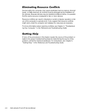
... problem or leads to two or more information about resolving conflicts, see Chapter 5, "Getting Help," in the Reference and Troubleshooting Guide. 2-6 Dell Latitude CP and CPi Service Manual Because devices may require dedicated memory spaces, interrupt levels, or DMA channels, all of which must be installed at all. Resource conflicts can ...If you suspect that the same resource is assigned to the proper troubleshooting steps for determining the source of the problem, call Dell for technical assistance. Devices within the computer may be allocated during installation of the devices.
... problem or leads to two or more information about resolving conflicts, see Chapter 5, "Getting Help," in the Reference and Troubleshooting Guide. 2-6 Dell Latitude CP and CPi Service Manual Because devices may require dedicated memory spaces, interrupt levels, or DMA channels, all of which must be installed at all. Resource conflicts can ...If you suspect that the same resource is assigned to the proper troubleshooting steps for determining the source of the problem, call Dell for technical assistance. Devices within the computer may be allocated during installation of the devices.
Service Manual
Page 28
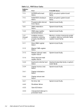
... faulty Display initialization failure Display retrace test failure No timer tick System board faulty Shutdown failure Gate A20 failure Unexpected interrupt in protected mode 3-2 Dell Latitude CP and CPi Service Manual 1-1-3 1-1-4 1-2-1 1-2-2 1-2-3 1-3-1 through 1-1-1 3-1-1 3-1-2 3-1-3 3-1-4 3-2-4 3-3-4 3-4-1 3-4-2 4-2-1 4-2-2 4-2-3 4-2-4 NVRAM write/read failure ROM BIOS checksum failure Programmable interval timer failure DMA initialization failure DMA page register write/read failure Installed memory...
... faulty Display initialization failure Display retrace test failure No timer tick System board faulty Shutdown failure Gate A20 failure Unexpected interrupt in protected mode 3-2 Dell Latitude CP and CPi Service Manual 1-1-3 1-1-4 1-2-1 1-2-2 1-2-3 1-3-1 through 1-1-1 3-1-1 3-1-2 3-1-3 3-1-4 3-2-4 3-3-4 3-4-1 3-4-2 4-2-1 4-2-2 4-2-3 4-2-4 NVRAM write/read failure ROM BIOS checksum failure Programmable interval timer failure DMA initialization failure DMA page register write/read failure Installed memory...
Service Manual
Page 30
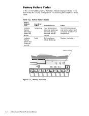
critical discharge Turn off the computer and let the battery and computer cool to room temperature. battery indicator 3-4 Dell Latitude CP and CPi Service Manual Indicator flashes alternately green and amber. In the event of a battery failure, the battery indicator displays indicator codes that identify the severity of the problem. The following table lists these failure codes. abnormal charge current Fatal Cell imbalance; Replace the battery. Temporary Over temperature; abnormal discharge; Indicator flashes amber four times per second. abnormal charge;
critical discharge Turn off the computer and let the battery and computer cool to room temperature. battery indicator 3-4 Dell Latitude CP and CPi Service Manual Indicator flashes alternately green and amber. In the event of a battery failure, the battery indicator displays indicator codes that identify the severity of the problem. The following table lists these failure codes. abnormal charge current Fatal Cell imbalance; Replace the battery. Temporary Over temperature; abnormal discharge; Indicator flashes amber four times per second. abnormal charge;

Service Manual
Page 32
.... PC Card software faulty or incorrectly installed. Hard-disk drive not responding to commands from computer. Message indicates system failure. Hard-disk drive faulty. 3-6 Dell Latitude CP and CPi Service Manual One or more memory modules faulty or improperly seated. Computer cannot identify hard-disk drive type. PC Card faulty, improperly seated, or improperly configured...
.... PC Card software faulty or incorrectly installed. Hard-disk drive not responding to commands from computer. Message indicates system failure. Hard-disk drive faulty. 3-6 Dell Latitude CP and CPi Service Manual One or more memory modules faulty or improperly seated. Computer cannot identify hard-disk drive type. PC Card faulty, improperly seated, or improperly configured...

Service Manual
Page 34
... external device faulty. No boot device available. Optional ROM in external device failed. Bad sector or corrupted FAT on diskette or hard-disk drive. 3-8 Dell Latitude CP and CPi Service Manual Installed memory module faulty or improperly seated. Memory double word logic failure at address, read value expecting value Memory odd/even logic failure at...
... external device faulty. No boot device available. Optional ROM in external device failed. Bad sector or corrupted FAT on diskette or hard-disk drive. 3-8 Dell Latitude CP and CPi Service Manual Installed memory module faulty or improperly seated. Memory double word logic failure at address, read value expecting value Memory odd/even logic failure at...
Service Manual
Page 36
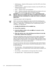
... of main memory (RAM) required for a thorough test of the automatic thermal management system. Runs selected tests from Dell. Follow these steps to isolate a failure Run All Tests - If you do not have a diskette-drive cable to...the diagnostics is detected, a message appears on the screen telling you which works with the air intake on contacting Dell. This menu lets you can get one from all tests for loading the diagnostics. Tests the SCSI controller in...or the C/Dock Expansion Station Audio - Tests a particular area or subsystem 3-10 Dell Latitude CP and CPi Service Manual
... of main memory (RAM) required for a thorough test of the automatic thermal management system. Runs selected tests from Dell. Follow these steps to isolate a failure Run All Tests - If you do not have a diskette-drive cable to...the diagnostics is detected, a message appears on the screen telling you which works with the air intake on contacting Dell. This menu lets you can get one from all tests for loading the diagnostics. Tests the SCSI controller in...or the C/Dock Expansion Station Audio - Tests a particular area or subsystem 3-10 Dell Latitude CP and CPi Service Manual

Service Manual
Page 38
Most of the procedures in suspend-to-disk mode. If you start to work on the computer, perform the following steps: NOTE: Make sure the computer is turned off and not in this guide require the use of one or more of the following tools: Number 1 magnetized Phillips-head screwdriver Small flat-blade screwdriver Small plastic scribe Before you cannot shut down the computer using the computer's operating system, press the power button for 4 seconds. 4-2 Dell Latitude CP and CPi Service Manual
Most of the procedures in suspend-to-disk mode. If you start to work on the computer, perform the following steps: NOTE: Make sure the computer is turned off and not in this guide require the use of one or more of the following tools: Number 1 magnetized Phillips-head screwdriver Small flat-blade screwdriver Small plastic scribe Before you cannot shut down the computer using the computer's operating system, press the power button for 4 seconds. 4-2 Dell Latitude CP and CPi Service Manual

Service Manual
Page 40
movable part of connector (do not remove) Some of the computer's interface connectors are not removable, but they must be released to disconnect a cable from them To disconnect an interface cable from a ZIF connector, follow these steps: To reconnect an interface cable to a ZIF connector, follow these steps: To ensure a firm connection, make sure the ZIF connector is completely closed. 4-4 Dell Latitude CP and CPi Service Manual These connectors are zero insertion force (ZIF) connectors.
movable part of connector (do not remove) Some of the computer's interface connectors are not removable, but they must be released to disconnect a cable from them To disconnect an interface cable from a ZIF connector, follow these steps: To reconnect an interface cable to a ZIF connector, follow these steps: To ensure a firm connection, make sure the ZIF connector is completely closed. 4-4 Dell Latitude CP and CPi Service Manual These connectors are zero insertion force (ZIF) connectors.
Service Manual
Page 42
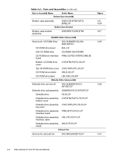
... CVR,TOP,PLSTC,CD,CP CD-ROM drive shield SHLD,CD,CP CD-ROM drive label LBL,REG,CD,20X Diskette drive service kit SVC,SUBASSY,FD,F3, 4-25 INT/EXT,CP Diskette drive subassembly SUBASSY,FD,F3,INT/EXT,CP Diskette drive FD,F3,CP Diskette drive assembly CVR,...CP bottom cover Diskette drive assembly CVR,TOP,PLSTC,FD,F3,CP top cover Diskette drive assembly PWA,INTFC,FD,F3,CP interface board Diskette drive assembly CBL,FPC,FD,F3,CP interface cable Diskette drive assembly SHLD,FD,F3,CP shield Service kit, exhaust fan SVC,FAN,25X25X10,CP 4-31 4-6 Dell Latitude CP and CPi Service Manual
... CVR,TOP,PLSTC,CD,CP CD-ROM drive shield SHLD,CD,CP CD-ROM drive label LBL,REG,CD,20X Diskette drive service kit SVC,SUBASSY,FD,F3, 4-25 INT/EXT,CP Diskette drive subassembly SUBASSY,FD,F3,INT/EXT,CP Diskette drive FD,F3,CP Diskette drive assembly CVR,...CP bottom cover Diskette drive assembly CVR,TOP,PLSTC,FD,F3,CP top cover Diskette drive assembly PWA,INTFC,FD,F3,CP interface board Diskette drive assembly CBL,FPC,FD,F3,CP interface cable Diskette drive assembly SHLD,FD,F3,CP shield Service kit, exhaust fan SVC,FAN,25X25X10,CP 4-31 4-6 Dell Latitude CP and CPi Service Manual

Service Manual
Page 44
...Display-assembly-bezel retaining screw covers, latch, 12.1-inch display Display top-cover service kit, 12.1-inch display Display top cover Display top-cover EMI shield SVC,BZL,LCD,12.1",CP BZL,LCD,TFT,12.1",CP CVR,SCR,TOP,RND,ADH CVR,SCR,BTM,OVAL,ADH CVR,SCR,TOP,OVAL,...SM,ADH,12.1 SVC,ASSY,CVR,TOP,LCD, 12.1",CP CVR,TOP,LCD,TFT,12.1",CP SHLD,EMI,DIS,TFT/STN, 12.1",CP 4-14, 4-17 4-8 Dell Latitude CP and CPi Service Manual Keyboard, Russian Keyboard, Spanish Keyboard, Swedish/Finnish Keyboard, Swiss Keyboard, Thailand Keyboard, U.K. Keyboard, U.S.
...Display-assembly-bezel retaining screw covers, latch, 12.1-inch display Display top-cover service kit, 12.1-inch display Display top cover Display top-cover EMI shield SVC,BZL,LCD,12.1",CP BZL,LCD,TFT,12.1",CP CVR,SCR,TOP,RND,ADH CVR,SCR,BTM,OVAL,ADH CVR,SCR,TOP,OVAL,...SM,ADH,12.1 SVC,ASSY,CVR,TOP,LCD, 12.1",CP CVR,TOP,LCD,TFT,12.1",CP SHLD,EMI,DIS,TFT/STN, 12.1",CP 4-14, 4-17 4-8 Dell Latitude CP and CPi Service Manual Keyboard, Russian Keyboard, Spanish Keyboard, Swedish/Finnish Keyboard, Swiss Keyboard, Thailand Keyboard, U.K. Keyboard, U.S.
Service Manual
Page 46
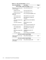
...,INVRTR,LCD,MYLAR, 13.3",CPX LCD cable subassembly, SUBASSY,CBL/HLDR,SMSNG, Samsung CPX LCD panel, Samsung LCD,TFT,XGA,13.3",CP, SMSNG LCD/Cable service kit, Sharp SVC,LCD/CBL/INV,SHARP, CPX LCD inverter board PWA,INVRTR,LCD,13.3",CPX LCD inverter board shield SHLD,INVRTR,...LCD,MYLAR, 13.3",CPX LCD cable subassembly, SUBASSY,CBL/HLDR,TFT, Sharp SHARP,CP LCD panel, Sharp LCD,TFT,XGA,13.3",CP,SHARP Latch service kit, 12.1-inch SVC,LATCH,DIS,BZL,CP 4-14 LCD display Latch service kit, 13.3-inch SVC,LATCH,DIS,BZL,CPX 4-15 LCD display 4-10 Dell Latitude CP and CPi Service Manual
...,INVRTR,LCD,MYLAR, 13.3",CPX LCD cable subassembly, SUBASSY,CBL/HLDR,SMSNG, Samsung CPX LCD panel, Samsung LCD,TFT,XGA,13.3",CP, SMSNG LCD/Cable service kit, Sharp SVC,LCD/CBL/INV,SHARP, CPX LCD inverter board PWA,INVRTR,LCD,13.3",CPX LCD inverter board shield SHLD,INVRTR,...LCD,MYLAR, 13.3",CPX LCD cable subassembly, SUBASSY,CBL/HLDR,TFT, Sharp SHARP,CP LCD panel, Sharp LCD,TFT,XGA,13.3",CP,SHARP Latch service kit, 12.1-inch SVC,LATCH,DIS,BZL,CP 4-14 LCD display Latch service kit, 13.3-inch SVC,LATCH,DIS,BZL,CPX 4-15 LCD display 4-10 Dell Latitude CP and CPi Service Manual


