Service Manual
Page 8
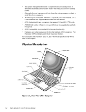
... upgraded by diskette if required. A BIOS that resides in flash memory and that support 5-V and 3.3-V PC Cards. display microphone power button keyboard touch pad battery bay touch pad buttons (2) modular bay display latch indicator panel cooling-fan air intake AC adapter connector audio jacks (3) speakers (2) 1-2 Dell Latitude CP and CPi Service Manual Two power.../2-compatible touch pad with IrDA 1.1 (Fast IR) and 1.0 standards, and a USB connector that supports stand-alone and hub devices. Hardware and software support for the Dell Latitude C/Port Advanced Port Replicator (APR) and...
... upgraded by diskette if required. A BIOS that resides in flash memory and that support 5-V and 3.3-V PC Cards. display microphone power button keyboard touch pad battery bay touch pad buttons (2) modular bay display latch indicator panel cooling-fan air intake AC adapter connector audio jacks (3) speakers (2) 1-2 Dell Latitude CP and CPi Service Manual Two power.../2-compatible touch pad with IrDA 1.1 (Fast IR) and 1.0 standards, and a USB connector that supports stand-alone and hub devices. Hardware and software support for the Dell Latitude C/Port Advanced Port Replicator (APR) and...
Service Manual
Page 14
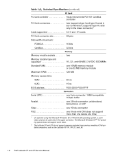
...Microsoft Windows NT ® 4.0 operating system does not support zoom video. 2 The Latitude CP and CPi do not support memory modules from previous models of Dell portable computers, such as the Latitude XP, XPi, XPi CD, and LM. 1-8 Dell Latitude CP and CPi Service Manual unidirectional, bidirectional, or ECP Video one 15-hole connector PS...RAM one 16-MB memory module or one 32-MB memory module Maximum RAM 128 MB Memory access time: tRAC 60 ns tCAC 15 ns BIOS address F000:0000-F000:FFFF Serial (DTE one 9-pin connector; 16550-compatible, 16-byte buffer Parallel one device at a time) 1 ...
...Microsoft Windows NT ® 4.0 operating system does not support zoom video. 2 The Latitude CP and CPi do not support memory modules from previous models of Dell portable computers, such as the Latitude XP, XPi, XPi CD, and LM. 1-8 Dell Latitude CP and CPi Service Manual unidirectional, bidirectional, or ECP Video one 15-hole connector PS...RAM one 16-MB memory module or one 32-MB memory module Maximum RAM 128 MB Memory access time: tRAC 60 ns tCAC 15 ns BIOS address F000:0000-F000:FFFF Serial (DTE one 9-pin connector; 16550-compatible, 16-byte buffer Parallel one device at a time) 1 ...
Service Manual
Page 28
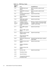
... test failure No timer tick System board faulty Shutdown failure Gate A20 failure Unexpected interrupt in protected mode 3-2 Dell Latitude CP and CPi Service Manual system board faulty BIOS corrupted; 1-1-3 1-1-4 1-2-1 1-2-2 1-2-3 1-3-1 through 1-1-1 3-1-1 3-1-2 3-1-3 3-1-4 3-2-4 3-3-4 3-4-1 3-4-2 4-2-1 4-2-2 4-2-3 4-2-4 NVRAM write/read failure ROM BIOS checksum failure Programmable interval timer failure DMA initialization failure DMA page register write/read failure Installed memory module...
... test failure No timer tick System board faulty Shutdown failure Gate A20 failure Unexpected interrupt in protected mode 3-2 Dell Latitude CP and CPi Service Manual system board faulty BIOS corrupted; 1-1-3 1-1-4 1-2-1 1-2-2 1-2-3 1-3-1 through 1-1-1 3-1-1 3-1-2 3-1-3 3-1-4 3-2-4 3-3-4 3-4-1 3-4-2 4-2-1 4-2-2 4-2-3 4-2-4 NVRAM write/read failure ROM BIOS checksum failure Programmable interval timer failure DMA initialization failure DMA page register write/read failure Installed memory module...
Service Manual
Page 47
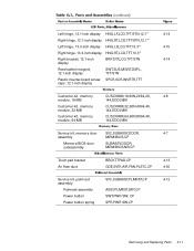
... SVC,SUBASSY,DOOR, 4-7 assembly MEM/BIOS,CP Memory/BIOS door subassembly SUBASSY,DOOR, MEM/BIOS,NB,CP Touch-pad bracket Air flow duct BRCKT,TPAD,CP 4-13 GDE,INTK,AIR,FAN,PLSTC,CP 4-30 Service kit, palmrest SVC,SUBASSY,PLMRST,CP 4-12 assembly Palmrest assembly ASSY,PLMRST,GRY,CP Power button SWT,PWR SW, CP Power button spring SPR,PWR...
... SVC,SUBASSY,DOOR, 4-7 assembly MEM/BIOS,CP Memory/BIOS door subassembly SUBASSY,DOOR, MEM/BIOS,NB,CP Touch-pad bracket Air flow duct BRCKT,TPAD,CP 4-13 GDE,INTK,AIR,FAN,PLSTC,CP 4-30 Service kit, palmrest SVC,SUBASSY,PLMRST,CP 4-12 assembly Palmrest assembly ASSY,PLMRST,GRY,CP Power button SWT,PWR SW, CP Power button spring SPR,PWR...
Service Manual
Page 84
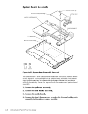
The replacement kit for the system board assembly includes a diskette that provides a utility for transferring the service tag number to the replacement system board assembly. 4-48 Dell Latitude CP and CPi Service Manual thermal cooling assembly system board assembly 2.5-mm screw bottom case assembly 2.5-mm screws (2) air flow duct 5-mm screws (2) The system board's BIOS chip contains the system service tag number, which is also visible on a bar-code label on the bottom of the computer.
The replacement kit for the system board assembly includes a diskette that provides a utility for transferring the service tag number to the replacement system board assembly. 4-48 Dell Latitude CP and CPi Service Manual thermal cooling assembly system board assembly 2.5-mm screw bottom case assembly 2.5-mm screws (2) air flow duct 5-mm screws (2) The system board's BIOS chip contains the system service tag number, which is also visible on a bar-code label on the bottom of the computer.
Service Manual
Page 85
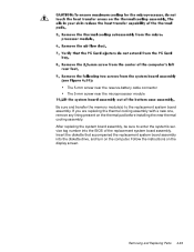
Insert the diskette that accompanied the replacement system board assembly into the BIOS of the replacement system board assembly. Follow the instructions on the thermal pad before installing the new thermal cooling assembly. Removing and Replacing Parts 4-49 ...
Insert the diskette that accompanied the replacement system board assembly into the BIOS of the replacement system board assembly. Follow the instructions on the thermal pad before installing the new thermal cooling assembly. Removing and Replacing Parts 4-49 ...

Replacement Instructions
Page 17
..., 7 assembly MEM/BIOS,CP Memory/BIOS door subassembly SUBASSY,DOOR, MEM/BIOS,NB,CP Touch-pad bracket Air flow duct BRCKT,TPAD,CP 13 GDE,INTK,AIR,FAN,PLSTC,CP 30 Service kit, palmrest SVC,SUBASSY,PLMRST,CP 12 assembly Palmrest assembly ASSY,PLMRST,GRY,CP Power button SWT,PWR SW, CP Power button spring SPR,PWR SW,CP Dell Latitude CP and CPi -
..., 7 assembly MEM/BIOS,CP Memory/BIOS door subassembly SUBASSY,DOOR, MEM/BIOS,NB,CP Touch-pad bracket Air flow duct BRCKT,TPAD,CP 13 GDE,INTK,AIR,FAN,PLSTC,CP 30 Service kit, palmrest SVC,SUBASSY,PLMRST,CP 12 assembly Palmrest assembly ASSY,PLMRST,GRY,CP Power button SWT,PWR SW, CP Power button spring SPR,PWR SW,CP Dell Latitude CP and CPi -
Replacement Instructions
Page 49
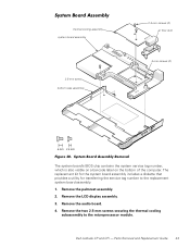
Remove the audio board. 4. Remove the LCD display assembly. 3. Remove the palmrest assembly. 2. Dell Latitude CP and CPi - Remove the two 2.5-mm screws securing the thermal cooling subassembly to the replacement system board assembly. 1. The replacement kit for the system board ... and Replacement Guide 43 thermal cooling assembly system board assembly 2.5-mm screw bottom case assembly 2.5-mm screws (2) air flow duct 5-mm screws (2) The system board's BIOS chip contains the system service tag number, which is also visible on a bar-code label on the bottom of the computer.
Remove the audio board. 4. Remove the LCD display assembly. 3. Remove the palmrest assembly. 2. Dell Latitude CP and CPi - Remove the two 2.5-mm screws securing the thermal cooling subassembly to the replacement system board assembly. 1. The replacement kit for the system board ... and Replacement Guide 43 thermal cooling assembly system board assembly 2.5-mm screw bottom case assembly 2.5-mm screws (2) air flow duct 5-mm screws (2) The system board's BIOS chip contains the system service tag number, which is also visible on a bar-code label on the bottom of the computer.
Replacement Instructions
Page 52
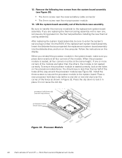
... processor module to the replacement system board assembly. Press the clip down clip (either a one -slot clip shown) processor-module fence holes 46 Dell Latitude CP and CPi - 12. If one , remove any lining present on the processor-module fence. Do not reuse the old clip. Be sure to... tag number into the diskette drive, and turn on the display. Insert the diskette that accompanied the replacement system board assembly into the BIOS of the bottom case assembly. When the processor module is not seated correctly. After replacing the system board assembly, be at the holes...
... processor module to the replacement system board assembly. Press the clip down clip (either a one -slot clip shown) processor-module fence holes 46 Dell Latitude CP and CPi - 12. If one , remove any lining present on the processor-module fence. Do not reuse the old clip. Be sure to... tag number into the diskette drive, and turn on the display. Insert the diskette that accompanied the replacement system board assembly into the BIOS of the bottom case assembly. When the processor module is not seated correctly. After replacing the system board assembly, be at the holes...


